
The WHY 2025 badge was never going to be a polite rectangle of laminated paper. Built for an outdoor hacker camp where attendees routinel monitors, tiny game consoles, and devices that confuse airport security, it was designed as a serious experimental computer.
On paper, the badge looked spectacular: a high-resolution square display, a physical keyboard, two ESP32 processors, LoRa connectivity, expansion pins, USB-C ports, and enough computing power to support ambitious applications. Then the batteries entered the conversation. More specifically, two unprotected 18650 lithium-ion cells entered the conversation, carrying enough electrical energy to turn a minor PCB mistake into a very warm networking opportunity.
The resulting controversy made the WHY 2025 badge one of the most instructive examples of modern “badgelife.” It demonstrated how open hardware, volunteer engineering, compressed schedules, power-hungry features, and battery safety can collide in one beautifully complicated object. hat Was the WHY 2025 Badge?
WHY2025, short for What Hackers Yearn 2025, was a nonprofit outdoor hacker camp held from August 8 through August 12, 2025, at Geestmerambacht in the Netherlands. It continued a long-running Dutch tradition of large hacker camps centered on experimentation, knowledge sharing, volunteer-built infrastructure, and projects that begin with, “This is probably possible,” rather than, “Has legal approved this?”
Electronic badges have become an important part of these events. Instead of merely proving that someone bought a ticket, a conference badge can serve as a development board, communications device, social game, electronic name tag, or foundation for community challenges. The best badges continue working long after the tents come down.
The WHY 2025 badge pushed that concept toward portable-computer territory. Its most visible feature was a bright 720-by-720-pixel IPS display paired with a compact QWERTY keyboard. The keyboard included backlighting and tactile feedback, making the badge look less like a name tag and more like a cyberdeck that had accidentally wandered onto a lanyard. nside the WHY 2025 Badge Hardware
The ESP32-P4 Compute Module
The primary processor was an ESP32-P4 mounted on a removable M.2-style compute module with a microSD card slot. Espressif designed the P4 for demanding human-machine interfaces and multimedia applications. It includes high-performance RISC-V processing cores, display and camera interfaces, hardware acceleration, USB support, and numerous peripheral controllers.
That architecture made sense for a badge driving a large square display. Rather than asking a small wireless microcontroller to perform every task while also keeping the screen responsive, the P4 could concentrate on graphics, applications, storage, and interface duties.
However, the ESP32-P4 does not provide the familiar integrated Wi-Fi and Bluetooth radios found in many other ESP32 devices. That job was assigned to a second processor. he ESP32-C6 Connectivity Processor
An ESP32-C6 handled wireless connectivity. The C6 combines 2.4 GHz Wi-Fi 6, Bluetooth Low Energy, and IEEE 802.15.4 support, the radio foundation used by technologies such as Thread and Zigbee. This gave the badge considerable networking potential, from ordinary Wi-Fi applications to experimental smart-home integrations.
Using separate compute and connectivity processors created a flexible platform, although it also added software and hardware complexity. The two chips had to communicate reliably, firmware had to coordinate their responsibilities, and developers had to understand which USB port and processor they were actually talking to. Nothing says “welcome to hardware development” quite like flashing the wrong chip before breakfast. oRa, Expansion Pins, and Other Maker-Friendly Features
The badge also included a LoRa radio module based on Semtech’s SX1262 family, allowing experimentation with long-range, low-bandwidth wireless communication. The official documentation warned users not to transmit without a properly installed antenna, because operating the radio without a suitable antenna could damage its output stage.
Additional hardware included GPIO connections, pogo-pin interfaces, camera and speaker connections, two USB-C ports, and opportunities for custom add-ons. One USB-C connection was associated with power and charging, while another provided access for development and communication.
This was not a badge designed around one predetermined game. It was intended as an open platform. Users could create applications, attach sensors, experiment with radio protocols, build status displays, or explore projects nobody had considered when the PCB was designed. hy Did the Badge Use Two 18650 Cells?
A large display, two processors, multiple radios, illuminated controls, and expansion hardware require considerably more energy than a few blinking LEDs. The designers chose two rechargeable 18650 lithium-ion cells connected in parallel.
In a parallel arrangement, the system retains approximately the voltage of a single lithium-ion cell while gaining additional capacity and current capability. That can provide longer operating time and better support for short bursts of high demand from the display, processor, backlight, or radios.
From a performance perspective, the choice was understandable. The 18650 format offers substantial energy density, is widely used in professionally engineered battery packs, and can power devices far more demanding than an ordinary conference badge.
The problem was not that 18650 technology is inherently unusable. The problem was the combination of unprotected cells, exposed construction, mechanical clearances, and portions of the electrical path that were not adequately protected against a short circuit.
The 18650 Safety Controversy
These Were Unprotected Industrial Cells
The cells distributed with the badge reportedly carried a manufacturer warning stating that consumers should not carry, use, or install them individually. They were unprotected cells intended to function as components inside properly engineered battery assemblies.
An unprotected cell generally lacks the small integrated protection circuit commonly added to consumer-oriented battery products. Such protection can disconnect a cell during dangerous conditions, including excessive charging voltage, excessive discharge, overcurrent, or a short circuit.
The U.S. Consumer Product Safety Commission has separately warned consumers about loose 18650 cells. According to the agency, exposed terminals can short against keys, coins, or other conductive objects, causing overheating, thermal runaway, fire, or an explosion. That warning is especially relevant to something worn around the neck, carried in a backpack, or tossed onto a workbench populated by screws, tools, and mysterious pieces of wire. he Dangerous Section Was Before the Protection
The badge did include protective components, including polyfuses. However, investigators highlighted that at least one positive battery trace traveled across a significant portion of the PCB before reaching its fuse.
A fuse can only protect circuitry downstream from its position. If a short occurs between the cell and the fuse, the fuse is not in the fault-current path and cannot perform its intended job. It is similar to installing a smoke detector in the garage after the garage has already driven away.
The concern was therefore not limited to someone deliberately connecting a wire between the battery terminals. A conductive object touching an exposed or damaged area on the unsafe side of the protection circuit could create a high-current path directly from the cells. older Mask Was Doing Too Much Work
Printed circuit boards are normally coated with solder mask, a thin resin layer that insulates copper and prevents solder from spreading where it does not belong. It is useful, but it is not a rugged structural enclosure.
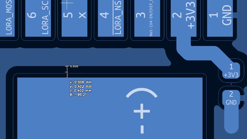
On the WHY 2025 badge, some positive copper regions and ground areas were separated by very small distances. The fire-hazard analysis reported approximately 0.4 millimeters between certain copper areas. It also found that the selected cell-holder tabs did not perfectly match the original PCB footprint, creating the possibility that manufacturing tolerances could leave a positive tab extremely close to, or overlapping, a ground region with only solder mask between them.
That might be acceptable inside a rigid enclosure where nothing scrapes the board. A badge is different. It swings from a lanyard, rubs against clothing, encounters metal zippers, shares bags with tools, and is handled by enthusiastic people who believe “bare PCB” is an invitation rather than a warning.
The same analysis also documented exposed battery-holder contacts and solder joints near opposite-polarity conductors. Damage, debris, jewelry, loose hardware, or ordinary wear could potentially bridge those points. he Destructive Test Was Difficult to Ignore
In a controlled test using an external 20-amp power supply, a MOSFET on the fault path reportedly became yellow-hot before the circuit opened. The investigators estimated that this indicated an extremely high component temperature.
The exact behavior of an actual cell-powered fault would depend on cell condition, contact resistance, fault location, and surrounding materials. Nevertheless, the test demonstrated the central issue: a component or copper path could become dangerously hot before naturally failing open.
When a circuit is worn against a shirt or stored beside paper, plastic, and fabric, “eventually the component burns apart” is not a reassuring protection strategy. ow the Organizers Responded
The safety concerns became public immediately before the event, when there was no practical time to redesign, manufacture, assemble, and test thousands of replacement boards.
Reported mitigations included applying epoxy resin over exposed battery-contact solder joints, distributing warnings, restricting badge distribution to very young children, and emphasizing that the badge could operate from USB-C power without the 18650 cells installed.
These steps reduced some immediate risks, especially the chance of a metal object bridging exposed solder joints. However, critics argued that epoxy over selected contacts did not correct every possible failure path, including traces located before the protective devices and partially exposed cell-holder areas.
The safest practical approach was therefore simple: remove the unprotected cells and power the badge from a reputable USB source with appropriate current limiting and short-circuit protection. Less portable? Yes. Less likely to turn a hoodie into a heating experiment? Also yes. hat Future Badge Designers Can Learn
Treat a Badge Like a Consumer Product
A conference badge may be experimental, open source, and assembled by volunteers, but it is still distributed to a large and diverse population. Some recipients are experienced electrical engineers. Others learned which end of a soldering iron gets hot earlier that morning.
Designers should assume foreseeable misuse, including reversed cells, mixed cells, damaged wrappers, loose coins, metal lanyard hardware, incorrect chargers, accidental drops, and storage in conductive environments.
Put Protection as Close to the Energy Source as Possible
Overcurrent protection should be positioned so that the smallest practical amount of conductor remains unprotected. Battery protection systems should address overvoltage, undervoltage, excessive charge or discharge current, short circuits, and, where appropriate, temperature.
For a mass-distributed device, it is generally better to use a professionally assembled battery pack with integrated protection, keyed connectors, strain relief, and mechanical insulation than to expose individual industrial cells.
Mechanical Design Is Electrical Design
A schematic can be electrically correct while the physical product remains unsafe. Cell holders, pad sizes, component tolerances, board edges, exposed contacts, enclosure materials, and abrasion paths all affect the real circuit.
The WHY 2025 badge showed why solder mask should not be the only barrier separating high-current battery conductors from objects in the outside world. A proper enclosure, insulating sheet, protected battery assembly, or carefully designed cell compartment can turn a fragile electrical assumption into a dependable mechanical safeguard.
Feature Creep Has a Power Cost
Every exciting feature increases power consumption, software complexity, assembly work, testing requirements, and failure opportunities. A large display leads to a larger battery. A larger battery raises fault energy. More processors create more firmware dependencies. More connectors create more mechanical variables.
That does not mean badges should be boring. It means ambitious features should be supported by equally ambitious verification. The flashy processor gets applause, but the humble fuse placement may be the component that saves the tent.
A Practical Experience With the WHY 2025 Badge
Based on the documented setup process and reports from owners, the post-event WHY 2025 badge experience begins with a decision: admire it as a collectible, power it carefully over USB-C, or dive into the firmware and turn it into something new.
The first impression is likely physical. This is a substantial badge. The square display and keyboard make it feel closer to a tiny handheld terminal than a traditional event token. It has the delightful overbuilt quality common to hacker hardware: nobody strictly needed a high-resolution display, two processors, LoRa, GPIO, and a keyboard hanging from one neck, which is precisely why the object is interesting.
For cautious owners, removing the 18650 cells changes the experience very little at a desk. Connected to a reputable USB power source, the badge can still boot, run applications, and serve as a development target. Portability becomes dependent on a protected power bank, but a short USB cable and a certified power bank are a reasonable compromise. The arrangement may look slightly less elegant, yet hacker events have never been famous for hiding their cables.
Software development introduces the next layer of adventure. Official instructions direct developers toward ESP-IDF and the ESP32-P4 target. A typical workflow involves installing the supported framework version, connecting to the correct USB-C port, compiling the firmware, flashing the badge, and opening the serial monitor. Developers can then create applications, edit manifests, rebuild the firmware, and test their work directly on the display. e hardware encourages experimentation but does not pretend to be a beginner-only board. Understanding the P4 and C6 relationship, storage layout, display stack, wireless firmware, and peripheral connections takes effort. A simple “Hello, world” app is achievable, but larger projects reward patience and careful reading. In other words, the badge offers the authentic embedded-development experience: ninety percent excitement, ten percent wondering why the serial port disappeared.
The keyboard and screen create project possibilities that ordinary microcontroller boards cannot match. An owner could build a compact SSH-style terminal, status dashboard, sensor interface, messaging experiment, portable documentation viewer, or control panel for home automation. Community requests and projects explored terminal applications, radio communication, games, alternative firmware, and even running lightweight Linux experiments on the hardware.
LoRa provides another tempting path, although it must be approached correctly. Before transmitting, the owner needs a suitable antenna and connector arrangement. Once configured, the badge can become a field messaging device, telemetry display, or experimental node. The experience is not quite “click one button and reach the horizon”; it is closer to “measure twice, attach the antenna, check the frequency rules, and then click the button.” e community-created cases and spacers also demonstrate how ownership extends beyond software. Volunteers collectively produced thousands of printed parts, while additional case designs appeared after the camp. A rear cover is especially valuable because it protects the PCB from abrasion, tools, conductive debris, and the general chaos of a maker’s backpack. timately, living with the WHY 2025 badge means accepting both sides of its personality. It is a powerful, open, unusual platform with real long-term project potential. It is also a reminder that impressive specifications cannot substitute for disciplined power-system design. Used from a protected USB source and handled thoughtfully, it can provide years of experimentation. Used casually with unprotected cells, it asks its owner to trust several design assumptions that should never have carried so much current.
Conclusion
The WHY 2025 badge deserves to be remembered as more than a battery controversy. Its ESP32-P4 compute module, ESP32-C6 connectivity, square display, keyboard, LoRa radio, and expansion interfaces created one of the most ambitious hacker badges of its generation.
At the same time, its 18650 implementation illustrated a fundamental engineering rule: safety must be designed into the complete system. A reputable cell does not make an unsafe layout safe. A fuse cannot protect conductors placed before it. Solder mask is not an enclosure, and warnings are not substitutes for electrical and mechanical safeguards.
That combination makes the badge genuinely valuable. It is a capable development platform, an unforgettable collectible, and a case study that future hardware teams can examine before ordering several thousand battery holders.