
Learning how to use an ohmmeter is one of those small skills that can make you feel like a wizard with test leads. One minute a mystery wire is “probably fine,” and the next minute your meter is calmly telling you, “Nope, this cable has betrayed you.” Whether you are fixing a lamp, checking a fuse, testing a speaker wire, or diagnosing a stubborn electronics project, an ohmmeter helps you measure resistance and continuity without guessing.
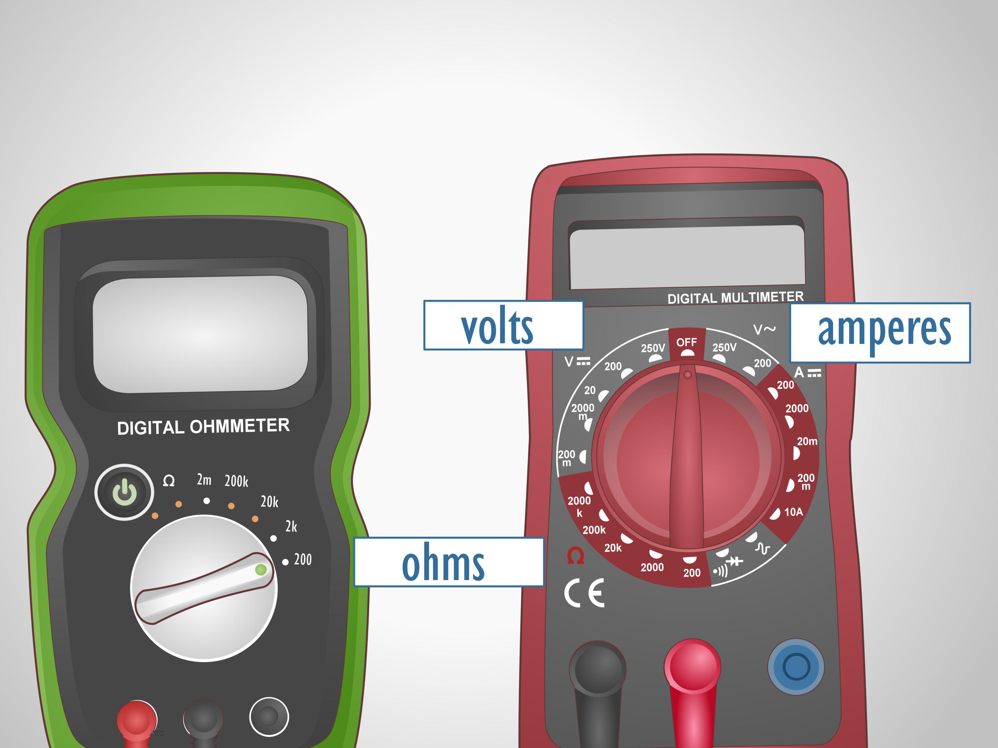
An ohmmeter measures electrical resistance in ohms, shown by the Greek omega symbol: Ω. Many people do not own a separate ohmmeter today because the function is built into most digital multimeters. When you turn the dial to the resistance setting, your multimeter becomes an ohmmeter. When you switch to continuity mode, it becomes a tiny truth detector that beeps when two points are electrically connected.
This guide explains how to use an ohmmeter to measure resistance and continuity safely, clearly, and with real-world examples. No engineering degree required. Just a meter, two probes, and the willingness to not poke live circuits like a curious raccoon.
What Is an Ohmmeter?
An ohmmeter is a measuring instrument used to find the resistance between two points in a circuit or component. Resistance is the opposition to the flow of electric current. A low resistance reading means electricity can move easily. A high resistance reading means electricity has a harder time moving. An open circuit reading means the path is broken.
Most modern ohmmeters are part of a digital multimeter, often called a DMM. A multimeter can usually measure voltage, current, resistance, continuity, and sometimes capacitance, temperature, frequency, or diodes. For this article, we are focusing on two of the most practical functions: resistance measurement and continuity testing.
Resistance vs. Continuity: What Is the Difference?
Resistance mode gives you a number, such as 0.4 Ω, 220 Ω, 1.2 kΩ, or 10 MΩ. It is useful when you want to know how much resistance a resistor, wire, switch, fuse, motor winding, or other component has.
Continuity mode answers a simpler question: “Are these two points connected?” Many meters beep when the resistance is low enough. The exact beep threshold depends on the meter. Some meters beep below about 25 ohms, others below 50 or 100 ohms. That means continuity mode is fast and convenient, but it is not always a precise resistance test.
Think of resistance mode as asking for the exact price of a sandwich. Continuity mode is asking, “Is there food in the building?” Both are useful. They just answer different questions.
Before You Start: Safety First
Before measuring resistance or continuity, always remove power from the circuit. This is the golden rule. An ohmmeter sends a small internal test current through the component being measured. If the circuit is already energized, the reading can be wrong, the meter can be damaged, and the user can be injured.
For household wiring, appliances, automotive systems, or anything connected to mains voltage, use extra caution. Unplug the device, turn off the breaker when appropriate, and verify that power is off with a properly rated meter before touching conductors. If you are not trained to work on line-voltage systems, call a qualified electrician. Pride is not a safety device.
Basic Safety Checklist
- Turn off and unplug the circuit or device before using resistance or continuity mode.
- Discharge capacitors before testing, especially in power supplies, amplifiers, microwaves, and motor circuits.
- Inspect test leads for cracked insulation, loose tips, or damaged plugs.
- Use the correct meter ports: black lead in COM, red lead in the Ω or VΩ jack.
- Never use resistance mode on a live circuit.
- Use a meter with the proper safety rating for the environment you are working in.
Parts of a Digital Ohmmeter or Multimeter
Most digital multimeters have three main parts: a display, a selector dial, and input ports. The display shows the reading. The dial chooses the function. The ports hold the test leads.
The black test lead usually plugs into the COM port. COM means common. The red test lead usually plugs into the port marked VΩ, Ω, or a combined symbol that includes voltage and resistance. Do not plug the red lead into the high-current port when measuring resistance. That port is for current measurements, and using it carelessly can turn your troubleshooting session into a very expensive lesson.
Common Symbols You Should Know
- Ω: resistance in ohms
- kΩ: kilohms, or thousands of ohms
- MΩ: megohms, or millions of ohms
- Continuity symbol: often looks like sound waves or a small speaker icon
- OL: overload, over limit, or open loop, often meaning the resistance is too high for the selected range
How to Use an Ohmmeter to Measure Resistance
Measuring resistance is simple once you understand the steps. The meter applies a small internal current, measures the response, and displays the resistance value. Here is the clean beginner-friendly process.
Step 1: Turn Off Power
Make sure the circuit is completely de-energized. If you are testing a loose resistor on a table, this is easy. If you are testing a component inside a device, unplug the device and confirm it is safe before continuing.
Step 2: Set the Meter to Ω
Turn the dial to the resistance setting marked Ω. If your meter is auto-ranging, it will choose the correct range automatically. If your meter is manual-ranging, start with a range higher than the resistance you expect. If you have no idea, start high and work downward until you get a stable reading.
Step 3: Plug in the Test Leads
Insert the black lead into COM and the red lead into the resistance input, usually labeled VΩ or Ω. Push the plugs in firmly. Loose test leads can cause jumpy readings, and jumpy readings make troubleshooting feel like reading tea leaves.
Step 4: Touch the Probe Tips Together
Before measuring your component, touch the probe tips together. A good meter and good leads should show very low resistance, often close to 0 Ω. You may see 0.1 Ω, 0.3 Ω, or a little more depending on the leads and meter. This is normal lead resistance.
If your meter shows a high value while the probes are touching, inspect the leads, clean the probe tips, or replace the battery. Dirty probe tips are tiny villains. They look harmless, but they love ruining measurements.
Step 5: Connect the Probes Across the Component
Place one probe on each side of the component or circuit path you want to test. Resistance is not directional for normal resistors, wires, switches, and fuses, so red and black probe placement usually does not matter. Hold the probes firmly and avoid touching the metal probe tips with your fingers, especially when measuring high resistance. Your body has resistance too, and your meter may include you in the reading like an unwanted guest star.
Step 6: Read the Display
The display may show a value in ohms, kilohms, or megohms. For example, a 1,000-ohm resistor may appear as 1.000 kΩ. A 10,000-ohm resistor may appear as 10.00 kΩ. A very high resistance may appear as MΩ, while an open circuit may show OL.
Examples of Resistance Readings
Here are practical examples to make the numbers feel less mysterious.
Testing a Resistor
Suppose you test a resistor marked as 1 kΩ. A normal reading may be around 0.99 kΩ to 1.01 kΩ for a tight-tolerance resistor, or a wider range for a cheaper part. Resistors are manufactured with tolerances, so a small difference from the labeled value is usually normal.
Testing a Fuse
A good fuse usually reads very close to 0 Ω because it should act like a continuous conductor. A blown fuse often reads OL or extremely high resistance. If a fuse looks fine but reads open, trust the meter. Clear glass can be sneaky.
Testing a Switch
When a switch is ON, the resistance across its terminals should be very low. When the switch is OFF, the meter should show OL or a very high resistance. If the switch reads high resistance when ON, the contacts may be dirty, worn, or damaged.
Testing a Wire or Cable
A short wire should read close to 0 Ω from one end to the other. Long wires can show slightly higher resistance. If the reading jumps around when you wiggle the cable, there may be an internal break or poor connector contact.
How to Use an Ohmmeter for Continuity Testing
Continuity testing is one of the most loved multimeter functions because it is fast. You do not even have to stare at the screen. The beep tells you whether two points are connected.
Step 1: Turn Off Power
As with resistance mode, continuity testing must be done on a de-energized circuit. Never use continuity mode on a live circuit.
Step 2: Select Continuity Mode
Turn the dial to the continuity symbol. On many meters, continuity shares a dial position with resistance, diode test, or capacitance. You may need to press a SELECT, MODE, or FUNC button to switch to the speaker icon.
Step 3: Touch the Probes Together
Touch the probe tips together. The meter should beep and show a low resistance value. This confirms that continuity mode is working.
Step 4: Test the Two Points
Place one probe on each point you want to check. If the meter beeps, the points are electrically connected with low resistance. If there is no beep, the circuit may be open, the resistance may be too high for the beep threshold, or you may be touching the wrong points.
Step 5: Confirm with Resistance Mode When Needed
Continuity mode is convenient, but it is not always enough. If you need to know whether a connection is truly excellent, switch to resistance mode and read the actual value. A circuit with 60 Ω of resistance may not beep on one meter but may beep on another. The number gives you better information.
Common Mistakes When Using an Ohmmeter
Even experienced people make meter mistakes. The difference is that experienced people have usually made them enough times to develop a suspicious squint.
Mistake 1: Testing Resistance on a Live Circuit
This is the big one. Resistance and continuity tests are for unpowered circuits only. Live voltage can damage the meter and create a shock hazard.
Mistake 2: Measuring Components In-Circuit Without Thinking
If a resistor is still connected to a circuit board, other components may create parallel paths. The meter measures everything connected between the probes, not just the resistor you are staring at. For accurate results, you may need to lift one leg of the component or remove it from the circuit.
Mistake 3: Ignoring Lead Resistance
When measuring very low resistance, the resistance of the test leads matters. If your leads measure 0.3 Ω when shorted together and your component reads 0.8 Ω, the component may actually be closer to 0.5 Ω. For precision low-resistance work, specialized meters or four-wire Kelvin measurements are used to reduce lead-resistance error.
Mistake 4: Holding Probe Tips with Your Fingers
Your body can affect high-resistance measurements. Hold the insulated parts of the probes instead of the metal tips.
Mistake 5: Misreading kΩ and MΩ
A reading of 4.7 kΩ is not 4.7 Ω. It is 4,700 Ω. A reading of 2.2 MΩ is 2,200,000 Ω. Those little letters matter. They are tiny, but they carry a lot of zeros.
Auto-Ranging vs. Manual-Ranging Ohmmeters
An auto-ranging meter chooses the range for you. This is convenient for beginners because the meter automatically displays Ω, kΩ, or MΩ as needed. The downside is that it may take a moment to settle on the final reading.
A manual-ranging meter requires you to choose the range yourself, such as 200 Ω, 2 kΩ, 20 kΩ, or 2 MΩ. If the range is too low, the display may show OL or 1. If the range is too high, the reading may be less precise. Manual-ranging meters are perfectly useful, but they require a little more attention.
What Does “OL” Mean on an Ohmmeter?
OL usually means the resistance is beyond the meter’s current range or the circuit is open. In resistance testing, OL can appear when the probes are not touching anything, when a wire is broken, when a switch is open, or when the selected manual range is too low.
If you are using a manual-ranging meter and see OL, move to a higher range. If the meter still shows OL at the highest range, the component or path is likely open or has extremely high resistance.
When Continuity Beeps but Something Still Is Not Right
A beep does not always mean a circuit is healthy. It only means the resistance is below the meter’s continuity threshold. For example, a corroded connector might still beep but have enough resistance to cause voltage drop under load. A wire strand may be barely touching inside a damaged cable and pass continuity with no load, then fail when moved.
That is why continuity testing is excellent for finding obvious opens, broken wires, blown fuses, and switch action, but resistance readings and real operating tests may still be needed for deeper troubleshooting.
Practical Uses for Resistance and Continuity Testing
Once you learn how to use an ohmmeter, you will find excuses to use it everywhere. It is useful for electronics, appliances, vehicles, hobbies, and home repairs.
Finding a Broken Wire
Set the meter to continuity mode and test from one end of the wire to the other. No beep means the wire is open or you are not on the same conductor. If the beep cuts in and out while you bend the wire, the conductor may be damaged internally.
Checking a Light Switch
With power off and the switch isolated, test across the switch terminals. ON should show low resistance or continuity. OFF should show OL. If the switch behaves unpredictably, replace it.
Testing a Heating Element
A heating element should usually show a measurable resistance, not a dead short and not an open circuit. The expected value depends on the device rating. If the element reads OL, it may be burned out.
Checking Speaker Wires
Continuity mode can identify which speaker wire goes where. Resistance mode can also help check whether a speaker voice coil is open. A speaker labeled 8 Ω may read somewhat lower with a basic DC resistance test, which is normal because impedance and DC resistance are not the same thing.
Experience Section: Lessons from Real-World Ohmmeter Use
The first practical lesson about using an ohmmeter is that the meter is only as honest as your setup. Many beginners blame the tool when the real problem is a loose probe, a dirty contact, or a component still connected to the rest of the circuit. If a reading looks strange, do not immediately declare the component “dead.” Check your range, check your leads, and test again. The meter is not magic, though it occasionally acts like it when it finds the exact broken wire you were mad at for twenty minutes.
A useful habit is to test the meter before testing the problem. Touch the probes together in resistance or continuity mode. You should see a very low value or hear a beep. Then separate the probes and confirm that the display shows OL or no continuity. This quick check takes five seconds and can save a lot of confusion. It also helps you learn what your meter considers “normal” for your leads.
Another lesson is to compare readings instead of relying on one measurement. For example, if you are testing several identical switches, fuses, wires, or resistors, measure a known-good one first. That gives you a reference. If five fuses read close to 0 Ω and one reads OL, the bad one has basically raised its hand and confessed.
When testing circuit boards, expect surprises. Components are often connected through parallel paths, coils, semiconductors, or other resistors. A resistor marked 10 kΩ may not read 10 kΩ while still soldered into a board. That does not automatically mean the resistor is bad. In-circuit measurements are excellent for quick clues, but accurate component testing often requires disconnecting one side of the part.
Continuity mode is especially helpful when tracing unknown wires. In automotive work, audio wiring, hobby electronics, and low-voltage projects, the beep can help you map a harness or cable without constantly looking at the screen. However, do not let the beep replace judgment. A weak connection, corrosion, or damaged strand may still pass a light continuity test but fail when real current flows.
For low-resistance work, lead resistance matters. If you are measuring a motor winding, a short cable, or a heavy conductor, first short the probes together and note the reading. If the leads read 0.4 Ω and the winding reads 1.2 Ω, the winding itself may be closer to 0.8 Ω. Basic meters are fine for general troubleshooting, but precision low-ohm measurements require better methods.
Finally, the best experience-based tip is simple: write down readings. When troubleshooting gets messy, memory becomes unreliable. A small note like “red-blue wire: OL” or “switch ON: 0.2 Ω” can prevent repeated testing and keep your brain from overheating. The ohmmeter gives facts. Your job is to organize those facts into a diagnosis.
Conclusion
Using an ohmmeter to measure resistance and continuity is one of the most valuable troubleshooting skills for electronics, electrical repairs, and everyday problem-solving. Resistance mode gives you actual ohm values, while continuity mode quickly tells you whether two points are connected. Together, they help identify broken wires, blown fuses, faulty switches, suspicious connectors, and components that are not behaving as expected.
The key is to work safely: turn off power, discharge capacitors, use the correct ports, inspect your test leads, and never measure resistance on a live circuit. Once those habits become automatic, an ohmmeter becomes less intimidating and much more useful. It is not just a tool for technicians. It is a pocket-sized detective for anyone who wants fewer guesses and better answers.
Note: This article is educational and intended for safe, de-energized resistance and continuity testing. For household mains wiring, high-voltage equipment, or repairs beyond your training, consult a qualified professional.