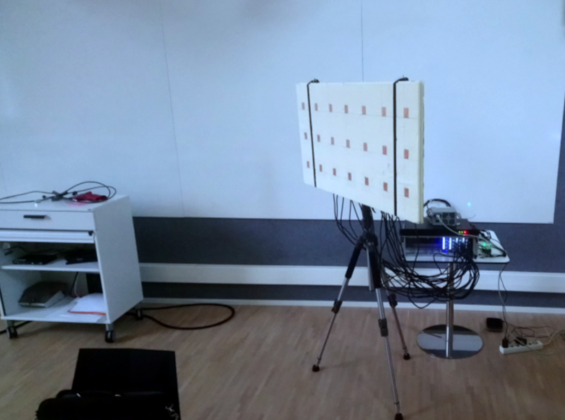

Phase coherent beamforming SDR sounds like something a radar engineer might whisper lovingly to an oscilloscope at 2 a.m. But behind the intimidating name is a beautifully practical idea: use multiple software-defined radio channels that agree on time and phase, then combine their signals so an antenna array can “listen” or “talk” in a chosen direction. Instead of spinning a big metal dish like a dramatic Cold War movie prop, the system steers energy electronically. No gears, no squeaky bearings, no heroic ladder climbing in bad weather.
In modern wireless research, radar prototyping, radio direction finding, satellite communication, passive sensing, 5G/6G experimentation, and electronic warfare testing, phase coherent SDR systems are increasingly important. They let engineers build flexible antenna arrays where much of the intelligence lives in software. That flexibility is the whole SDR bargain: move signal processing out of fixed hardware and into code, where algorithms can be changed, improved, broken, fixed, and broken again before lunch.
This article explains what phase coherent beamforming SDR means, why coherence matters, how the hardware and software fit together, what can go wrong, and how real-world builders approach calibration without losing their sanity.
What Is Phase Coherent Beamforming SDR?
A software-defined radio, or SDR, is a radio platform where functions such as tuning, filtering, demodulation, modulation, and signal analysis are handled largely in software. A basic SDR may have one receive channel. A more advanced system may have two, four, eight, sixteen, or even more synchronized RF channels connected to an antenna array.
Beamforming is the process of combining signals from multiple antenna elements with carefully chosen amplitude and phase weights. On receive, beamforming can increase sensitivity in one direction and reduce interference from another. On transmit, it can focus radiated energy toward a target region. In plain English: the array becomes picky about where it listens and where it shouts.
Phase coherent beamforming SDR means the system preserves a known phase relationship among all radio channels. If channel one says a waveform peak arrived now, channel two must agree closely enough that software can compare the difference. That tiny phase difference is not noise; it is the clue that tells the system where the signal came from.
Why Phase Coherence Matters
Imagine four people trying to push a stalled car. If everyone pushes together, the car moves. If one person pushes, one pulls, and two argue about sample clocks, the car stays parked. Antenna arrays behave similarly. Signals from different elements must add constructively in the desired direction. If phase relationships drift unpredictably, the beam gets blurry, weak, or aimed at the neighbor’s garage door instead of the intended signal source.
For direction-of-arrival estimation, phase coherence is essential because the system uses differences in signal arrival time and phase across antenna elements. For MIMO communication, coherence helps separate spatial streams and improve link performance. For radar, coherent processing improves detection, resolution, and target tracking. For passive radar and radio astronomy, phase stability can determine whether the result is useful data or expensive modern art.
Coherent vs. Non-Coherent SDR Channels
Two SDRs tuned to the same frequency are not automatically phase coherent. They may have separate oscillators, independent local oscillator phase, unrelated sampling clocks, and different analog path delays. They can receive the same station beautifully and still be useless for precision beamforming unless their timing and phase relationships are known, stable, or regularly calibrated.
A phase coherent SDR setup typically needs shared or aligned sample clocks, deterministic timing, synchronized start of streaming, and either shared local oscillators or a calibration method that measures phase offsets. The exact solution depends on the hardware. Some SDR platforms provide built-in synchronization features; others require external references, trigger lines, clock distribution, calibration tones, or clever over-the-air correction.
The Core Building Blocks of a Beamforming SDR System
1. Antenna Array Geometry
The antenna array is the physical foundation of the beamformer. Common arrangements include uniform linear arrays, uniform rectangular arrays, circular arrays, and sparse arrays. A uniform linear array is easy to understand and useful for experiments, while rectangular arrays support two-dimensional angle estimation. Sparse arrays reduce the number of required RF channels while preserving useful aperture characteristics, although they require more careful processing.
Element spacing matters. A common design target is half-wavelength spacing at the operating frequency. Wider spacing can create grating lobes, which are unwanted duplicate beams. Smaller spacing can reduce aperture and angular resolution. Antenna matching, cable routing, polarization, mounting accuracy, and nearby objects also matter. In RF, “close enough” sometimes means “congratulations, you built a multipath sculpture.”
2. Multi-Channel SDR Hardware
Beamforming requires multiple RF channels. Platforms often used in research include USRP-class radios, multi-channel SDR boards, direct RF sampling systems, and synchronized low-cost receiver arrays. Higher-end systems may support local oscillator sharing, external 10 MHz references, pulse-per-second timing, deterministic latency, FPGA processing, and wide instantaneous bandwidth. Lower-cost systems can still demonstrate powerful concepts, especially on receive, but usually demand more calibration work.
The key hardware questions are simple but unforgiving: Do all channels share the same sample clock? Can they start at a known time? Is local oscillator phase repeatable or measurable? How stable are the analog paths after retuning, rebooting, or warming up? Is the host interface fast enough to stream all channels without dropped samples? Beamforming is not only an RF problem; it is also a data plumbing problem wearing an antenna hat.
3. Clock and Timing Synchronization
Time alignment is the first major requirement. Multi-channel systems must capture samples that correspond to the same instant. This usually involves a common reference clock, synchronized sample clocks, hardware triggers, timestamped streaming, or a timing signal such as PPS. Without timing synchronization, phase comparison becomes unreliable because the samples are not truly comparable.
Clock synchronization also reduces frequency drift between channels. If each channel runs from a different oscillator, the relative phase may rotate over time. That rotation might be slow enough to watch or fast enough to ruin the measurement before the coffee cools. A shared clock keeps channels marching to the same drummer.
4. Local Oscillator and Phase Alignment
Even when sample clocks are aligned, the RF mixing stage can introduce phase ambiguity. Local oscillators and phase-locked loops may start with different phase states each time the device tunes or powers up. Some hardware supports local oscillator sharing, which improves repeatability across channels. Other systems require a calibration signal to measure offsets.
A common approach is to inject a known tone, noise source, or reference signal into all channels. The software measures relative phase differences and applies correction weights. In receive beamforming, the correction may be as simple as multiplying each channel by a complex coefficient. In transmit beamforming, the correction must also account for power amplifier behavior, cable length, antenna response, and regulatory limits.
How Beamforming Works in Software
At baseband, each SDR channel produces complex I/Q samples. These samples contain amplitude and phase information. A digital beamformer multiplies each channel by a complex weight and sums the results. The weight controls phase shift and gain. By choosing the right weights, the software causes signals from a desired direction to line up and add together.
For a narrowband signal arriving at a linear array, the phase shift between adjacent elements depends on frequency, element spacing, and arrival angle. Once the system estimates or selects the target angle, it computes weights that compensate for those phase differences. The desired signal adds coherently, while signals from other directions combine less effectively or cancel.
Conventional Beamforming
Conventional beamforming, sometimes called delay-and-sum beamforming, uses fixed steering weights. It is straightforward, predictable, and excellent for learning. You choose a steering angle, calculate phase shifts, combine channels, and inspect the resulting array pattern. It is the “hello world” of phased array signal processing, except the hello arrives at a suspicious bearing of 37 degrees.
Adaptive Beamforming
Adaptive beamforming changes weights based on the signal environment. Algorithms such as MVDR, LCMV, and related optimization methods can preserve gain in a desired direction while placing nulls toward interference. These methods are powerful but more sensitive to calibration errors, covariance estimation, sample quality, and model mismatch. Adaptive beamforming is where the math starts wearing a lab coat.
Direction-of-Arrival Algorithms
Phase coherent SDR arrays are often used for direction finding. Algorithms such as MUSIC and ESPRIT estimate the angle of incoming signals by analyzing phase relationships across antenna elements. These methods can achieve impressive resolution when the signal model is appropriate and the array is well calibrated. They can also become dramatically wrong when antennas are misplaced, signals are multipath-rich, or channels quietly drift out of coherence.
Common Applications of Phase Coherent Beamforming SDR
Radio Direction Finding
Radio direction finding is one of the most approachable applications. A coherent receiver array listens to a signal and estimates its bearing. This can be useful for locating interference, tracking beacons, studying spectrum use, or building educational demos. Even modest arrays can show clear directional behavior when calibration and antenna placement are handled carefully.
Passive Radar
Passive radar systems use existing transmitters, such as broadcast or communication signals, as illuminators. A coherent SDR setup can compare reference and surveillance channels to detect reflections from moving objects. This requires careful synchronization and signal processing, but it demonstrates why coherent multi-channel receiving is so valuable: the system extracts information from phase, delay, and Doppler rather than simply asking whether a signal is loud.
5G, 6G, and Massive MIMO Research
Modern wireless systems use beamforming to improve coverage, capacity, and spectral efficiency. SDR platforms allow researchers to prototype MIMO links, test synchronization methods, evaluate beam training, and experiment with hybrid or digital beamforming. As networks move toward higher frequencies and larger arrays, phase alignment becomes even more important because small physical errors represent larger phase shifts.
Radar and Sensing
Coherent beamforming is central to radar. Digital arrays can steer beams, form multiple beams, suppress clutter, and estimate target angle. SDR-based radar prototypes are especially attractive in labs because researchers can modify waveforms and algorithms without rebuilding the entire RF chain. The tradeoff is that the system must maintain phase stability well enough for meaningful coherent processing.
Satellite and Space Communications
Beamforming can help ground stations track satellites, improve gain, and reduce interference. SDR arrays can support experimentation with electronically steered antennas, signal acquisition, and multi-antenna reception. The same principles apply: know the geometry, synchronize the channels, calibrate the phase, and do not assume the universe will forgive sloppy cables.
Calibration: The Part Everyone Underestimates Once
Calibration is where elegant theory meets the drawer full of coax adapters. A beamforming SDR system needs calibration because each channel has its own analog path. Cables have different electrical lengths. Filters introduce phase response. Mixers, amplifiers, connectors, antennas, and PCB traces all add their own small personality disorders.
A practical calibration workflow usually begins with a common reference signal. The signal is distributed to all receive channels through a splitter, coupler network, noise source, or calibration antenna. The system measures the relative phase and amplitude response of each channel, then stores correction coefficients. During operation, incoming I/Q samples are corrected before beamforming or direction estimation.
Calibration may need to be repeated after changing frequency, gain, sample rate, antennas, cables, temperature, power state, or local oscillator settings. Some systems remain stable for long sessions. Others drift like a shopping cart with one bad wheel. Good engineering means measuring stability instead of assuming it.
Hardware Challenges in Real SDR Beamforming
Sample Drops and Host Throughput
Multi-channel SDR creates large data streams. Four channels at high sample rates can already stress USB, Ethernet, PCIe, storage, and CPU resources. Eight or sixteen channels raise the stakes. Dropped samples break time alignment and can corrupt phase measurements. A stable system often needs careful buffer sizing, efficient data formats, FPGA offload, and realistic bandwidth choices.
Frequency-Dependent Phase Offsets
Phase calibration at one frequency does not always apply at another. Cable delay and analog filters create frequency-dependent phase shifts. Wideband beamforming may require true time delay, subband processing, or frequency-dependent correction. A narrowband beamformer can get away with phase shifts; a wideband beamformer must think harder.
Mutual Coupling and Antenna Effects
Antenna elements interact with each other, especially when closely spaced. This mutual coupling changes the effective response of each element and can distort beam patterns. Real arrays also suffer from mounting tolerances, polarization mismatch, ground reflections, and nearby objects. The antenna array is not an abstract diagram; it is a physical object living in a messy electromagnetic neighborhood.
Regulatory and Safety Limits
Receive-only experiments are usually simpler from a regulatory perspective. Transmit beamforming requires appropriate authorization, frequency selection, power control, spectral cleanliness, and compliance with applicable rules. A phase coherent transmit array is not a toy megaphone. It can focus RF energy, interfere with other systems, and attract attention from people with clipboards.
Software Tools and Processing Pipelines
Phase coherent beamforming SDR projects commonly use environments such as GNU Radio, MATLAB, Simulink, Python with NumPy and SciPy, vendor SDR APIs, FPGA toolchains, and custom C++ pipelines. The best choice depends on latency, bandwidth, hardware support, algorithm complexity, and whether the goal is education, research, or deployment.
A typical receive pipeline starts with synchronized I/Q capture. Next comes channel correction, filtering, decimation, calibration verification, beamforming, detection, visualization, and logging. For direction finding, the pipeline may compute covariance matrices, scan steering vectors, and produce an angle spectrum. For adaptive beamforming, it may update weights continuously as interference changes.
Visualization is not optional. Plotting per-channel phase, amplitude, spectrum, correlation, beam pattern, and estimated angle over time can reveal problems quickly. Without plots, debugging beamforming feels like tuning a piano in another room using only text messages.
Best Practices for Building a Phase Coherent SDR Array
Start Narrowband and Small
Begin with two channels before scaling to many. Use a clean single-tone source or known transmitter. Verify that phase difference remains stable. Then add antennas, steering calculations, and angle estimation. A small working system teaches more than a large mysterious one.
Control the Clocking Architecture
Use a shared reference clock when possible. Confirm that all devices lock to it. Use hardware timestamps or triggers to align streams. Document the configuration so the setup can be repeated. Beamforming hates mystery, especially clock mystery.
Measure Before Trusting
Measure phase offsets, amplitude imbalance, noise floor, sample drops, drift over time, and repeatability after retuning. If the system behaves differently after every restart, build calibration into the workflow rather than treating it as a one-time ceremony.
Keep Cables Boring
Use equal-length cables when practical, label everything, avoid loose connectors, and secure the array mechanically. Boring cables are good cables. Exciting cables are usually the reason the beam points at the ceiling.
Respect the Environment
Multipath can dominate indoor tests. Reflections from walls, desks, racks, and human bodies can confuse angle estimates. Outdoor testing, absorber material, elevated antennas, or controlled lab setups can help. When results look strange, the room may be part of the experiment.
Specific Example: A Four-Channel Receive Beamformer
Consider a four-element linear array operating at 915 MHz with half-wavelength spacing. Each antenna connects to one coherent SDR receive channel. The system uses a shared 10 MHz reference and synchronized streaming. A calibration tone is injected through a splitter so the software can measure relative phase offsets. After correction, the software applies steering weights for angles from -90 to +90 degrees and computes output power for each steering direction.
When a transmitter is placed broadside to the array, the beam scan should show a peak near 0 degrees. Move the transmitter to one side, and the peak should shift accordingly. Add an interfering source, and an adaptive beamformer may reduce its impact by placing a null. The demo is simple, but it contains the essential ingredients of larger phased array systems: geometry, synchronization, calibration, complex weights, and validation.
Experience Notes: What Working With Phase Coherent Beamforming SDR Teaches You
The first lesson from hands-on phase coherent beamforming SDR work is that the math is usually cleaner than the bench. Equations assume perfect clocks, identical channels, stable oscillators, and antennas that behave like well-trained golden retrievers. Real hardware behaves more like four cats in a trench coat. Each channel has its own offset, each cable has its own delay, and each connector has a secret opinion about your project schedule.
A practical workflow becomes part engineering and part ritual. Power the system. Let it warm up. Confirm the reference lock. Start the streams. Check for overruns. Run calibration. Save coefficients. Verify phase stability. Then, and only then, trust the beam plot. Skipping these steps may still produce a graph, but graphs are polite; they will not always tell you they are lying.
One common experience is discovering that a beautiful simulation fails in the lab because the antenna spacing is slightly wrong or the test signal is bouncing off a filing cabinet. Multipath can create multiple apparent directions, especially indoors. The beamformer may not be broken; it may simply be telling the truth about an ugly RF environment. Moving the array a few feet, raising it off the bench, or testing outdoors can suddenly make the results look sensible.
Another memorable lesson is that calibration is not a checkbox. It is a habit. You may calibrate the system at 900 MHz and get excellent results, then retune to 950 MHz and wonder why the array has developed a dramatic new personality. Frequency changes alter phase relationships. Gain changes can affect response. Temperature drift can nudge measurements. Power cycling may reset local oscillator phase. Good systems either maintain deterministic coherence or make recalibration fast and routine.
Debugging usually improves when you simplify. If a four-channel array looks wrong, reduce it to two channels. If the antennas look wrong, replace them with a splitter-fed reference signal. If the beam scan looks chaotic, plot raw phase difference over time. If the phase is rotating, look for clock or frequency offset. If the phase jumps, look for dropped samples, retuning events, or unstable synchronization. The fastest path forward is often not a cleverer algorithm but a smaller experiment.
Phase coherent SDR also teaches respect for data movement. A high-rate multi-channel capture can overwhelm a host computer quickly. It is tempting to request wide bandwidth because wide bandwidth feels powerful. Then the system drops samples, the phase alignment breaks, and the powerful configuration becomes a very expensive random number generator. Sensible sample rates, decimation, FPGA preprocessing, and efficient streaming are not boring details; they are what keep the beamformer alive.
The most satisfying moment is when the array finally behaves. You rotate a signal source, rerun the scan, and the peak moves exactly where expected. You add an interferer, apply adaptive weights, and watch a null appear. Suddenly the abstract phrase “spatial filtering” becomes visible. The array is no longer just receiving radio waves; it is interpreting space. That is the magic of phase coherent beamforming SDR: with synchronized hardware and smart software, a handful of antennas becomes an instrument that can hear direction.
Conclusion
Phase coherent beamforming SDR combines antenna arrays, synchronized radio hardware, calibration, and digital signal processing to create steerable spatial sensitivity. It is a core technique behind modern direction finding, MIMO research, radar, passive sensing, satellite communication, and advanced wireless experimentation. The main idea is simple: preserve known phase relationships across multiple SDR channels so software can combine signals intelligently.
The execution is less simple, but that is where the fun begins. Reliable systems require shared timing, stable phase, careful calibration, realistic bandwidth, clean data streaming, thoughtful array geometry, and constant measurement. When those pieces come together, SDR beamforming becomes one of the most flexible and exciting ways to explore the radio world.
Note: This article is intended for educational and technical publishing purposes. Transmit experiments should always follow applicable spectrum regulations, licensing requirements, and RF safety practices.