
Note: This article is for educational and informational purposes. Linear power supplies can involve mains voltage, large capacitors, heat, and stored energy. Anyone building one should follow electrical codes, use properly rated components, and get help from a qualified person when working beyond low-voltage circuits.
A simple linear power supply sounds almost too humble to deserve attention. It does not brag about high-frequency switching, digital control loops, gallium nitride transistors, Bluetooth dashboards, or any other feature that makes a spec sheet look like it has been doing push-ups. It is usually just a transformer, a rectifier, a smoothing capacitor, and maybe a voltage regulator. That is the entire orchestra: four instruments, no fog machine.
Yet when a linear power supply is designed well, it can be one of the most dependable pieces of electronics on the bench. It can deliver clean DC voltage, low ripple, predictable behavior, and a kind of quiet confidence that sensitive audio circuits, analog test equipment, control systems, and hobby electronics appreciate. In a world where switching power supplies dominate because they are smaller and more efficient, the linear regulated power supply remains the old cast-iron skillet of electronics: heavy, simple, not fashionable, and still excellent when used correctly.
The trick is in the phrase “done well.” A poor linear PSU is just a hot box with a voltage problem. A good one is designed around real load current, transformer headroom, capacitor ripple, regulator dropout, heat dissipation, grounding, protection, and safety. In other words, simplicity does not excuse laziness. It demands discipline.
What Is a Linear Power Supply?
A linear power supply converts AC power into DC power using a straightforward sequence. First, a transformer steps the AC voltage up or down and provides isolation from the mains. Second, a rectifier converts AC into pulsating DC. Third, filter capacitors smooth that pulsing waveform into a more stable DC level. Finally, a regulator may hold the output voltage steady as input voltage, load current, and temperature change.
That architecture is easy to understand, which is why many electronics learners meet it early. But it is not just a beginner circuit. Laboratory bench supplies, audio amplifier supplies, instrumentation rails, radio equipment, and industrial control modules have all used linear designs because they can be quiet, rugged, and easy to troubleshoot. If a switching supply is a sports car with a turbocharger, a linear supply is a pickup truck with a manual transmission. It may not win the efficiency race, but it will get the job done without asking for firmware updates.
Why Build a Linear Supply When Switching Supplies Exist?
Switching power supplies are everywhere for good reasons. They are efficient, compact, lightweight, and inexpensive at scale. Phone chargers, laptop adapters, LED drivers, and embedded systems often rely on switch-mode power supplies because heat and space matter. A linear power supply, by comparison, wastes the extra voltage as heat. That is not a tiny flaw; it is the main trade-off.
Still, linear supplies have advantages. They generate less high-frequency noise, require fewer complex parts, and are easier to repair. For analog circuits, audio projects, sensor interfaces, and low-noise reference rails, a carefully designed linear regulator can be the calmer choice. The question is not “Which technology is better?” The question is “Which supply fits the job?” Using a switching converter to power a sensitive preamp can work beautifully if filtered well. Using a linear supply can also work beautifully with fewer noise-management gymnastics.
The Core Building Blocks of a Good Linear PSU
1. The Transformer: More Than a Heavy Lump
The transformer is the first serious design decision. It sets the available voltage and current, provides isolation, and strongly influences heat. A common mistake is choosing a transformer with too much secondary voltage “just to be safe.” That sounds responsible until the regulator starts cooking like a tiny silicon pancake.
After rectification and filtering, the DC voltage is roughly the transformer’s AC RMS voltage multiplied by 1.414, minus diode drops, under ideal conditions. A 12 VAC secondary does not become 12 VDC after smoothing; it can rise toward 16 VDC or more with light loading. Under load, transformer regulation, ripple, and line variation pull that number down. A well-designed supply leaves enough headroom for the regulator but not so much that the extra voltage becomes unnecessary heat.
For audio amplifier power supplies, toroidal transformers are popular because they are compact for their VA rating and can have lower stray magnetic fields than traditional laminated transformers. But toroids are not magic donuts. They still need correct fusing, mounting, insulation, and inrush-current consideration.
2. The Rectifier: Turning AC Into Usable DC
A bridge rectifier uses four diodes to convert both halves of the AC waveform into pulsating DC. It is efficient in transformer usage because it does not require a center-tapped secondary. However, two diodes conduct at any moment, so their forward voltage drops must be included in the design. At higher currents, that voltage drop becomes heat in the rectifier package.
Choose rectifier diodes or a bridge module with comfortable current and reverse-voltage ratings. In real supplies, current through the rectifier is not a smooth gentle stream. The smoothing capacitor charges in short pulses near the peaks of the AC waveform, so peak currents can be much higher than average load current. This is why “1 amp output” does not automatically mean “a 1 amp rectifier is fine.” Electronics has a long tradition of punishing assumptions, usually with smoke.
3. The Filter Capacitor: The Reservoir That Matters
The smoothing capacitor stores charge between rectified peaks. In a full-wave rectified 60 Hz system, the capacitor is refreshed 120 times per second. The larger the load current, the faster the capacitor discharges between peaks, and the more ripple appears on the unregulated DC rail.
A useful approximation for capacitor sizing is:
C = I / (2 × f × Vripple)
Here, I is load current, f is mains frequency, and Vripple is the acceptable ripple voltage before the regulator. For example, a 1 A load on a 60 Hz full-wave rectified supply with 1 V of ripple would require about 8,300 microfarads. In practice, designers add margin, check capacitor ripple-current ratings, choose a suitable voltage rating, and consider temperature. Electrolytic capacitors age faster when hot, so putting them next to a regulator heatsink is like storing chocolate on a radiator: technically possible, emotionally questionable.
4. The Regulator: Where Precision Meets Heat
The voltage regulator is what turns a decent DC rail into a steady output. Classic regulators such as 78xx fixed regulators, LM317 adjustable regulators, and modern low-dropout regulators all use a pass element to maintain output voltage. The cost of this elegance is heat.
The basic power dissipation equation is simple:
P = (Vin - Vout) × Iout
If a regulator receives 16 V and outputs 12 V at 1 A, it dissipates 4 W as heat. Four watts may not sound dramatic until it is trapped in a small plastic enclosure with no airflow. If that same regulator outputs 5 V from 16 V at 1 A, it must dissipate 11 W. At that point, the regulator is no longer a regulator; it is a toaster with opinions.
A good linear power supply minimizes unnecessary voltage drop, uses a regulator with suitable dropout voltage, includes the required input and output capacitors, and provides enough heatsinking. Data sheets matter. Some LDOs are picky about output capacitor ESR. Some regulators need protection diodes when large capacitors are used. Some have thermal shutdown, but thermal shutdown should be treated like an emergency brake, not a cooling strategy.
Linear Power Supply Design Example
Imagine a small 12 VDC linear regulated power supply for a low-noise preamp or control circuit drawing up to 500 mA. A designer might begin with a 15 VAC transformer, a bridge rectifier, a 4,700 to 6,800 microfarad filter capacitor, and a 12 V regulator. Under light load, the unregulated DC rail might be around 20 V. Under load, it may settle lower depending on transformer regulation and ripple. The regulator needs enough headroom at the ripple valleys to stay in regulation.
But the thermal check is just as important. If the regulator averages 18 V in and 12 V out at 0.5 A, it dissipates about 3 W. That likely requires a heatsink and ventilation. If the transformer secondary can be reduced while preserving dropout margin, the supply becomes cooler and more reliable. This is the heart of good linear PSU design: do not merely make the voltage work; make the heat work.
Protection: The Difference Between Robust and Regretful
A linear power supply should include protection features appropriate to its environment. At minimum, mains-powered supplies need a correctly rated fuse, safe switch wiring, strain relief, proper grounding, and an enclosure that prevents accidental contact with dangerous voltages. A metal enclosure should be bonded to protective earth. Exposed primary wiring should be insulated and physically separated from low-voltage circuitry.
On the low-voltage side, consider output fuses or current limiting, reverse-polarity protection, bleeder resistors for large capacitors, transient suppression, and clear labeling. A power indicator LED is also helpful, not because LEDs are glamorous, but because capacitors can remain charged after the switch is off. A bleeder resistor gives that stored energy a safe path to discharge.
Bench supplies should also handle abuse. Real users short outputs, connect loads backward, and turn knobs before coffee. Current limiting, thermal design, and conservative component ratings keep these small accidents from becoming dramatic learning experiences.
PCB Layout and Grounding: Quiet Supplies Are Built, Not Wished Into Existence
A linear power supply may be electrically simple, but layout still matters. High-current charging pulses flow between the transformer secondary, rectifier, and bulk capacitor. Keep those loops short and heavy. Do not route sensitive regulator feedback traces through noisy charging-current paths. Use wide copper for high-current rails and plan the return paths deliberately.
For low-noise analog or audio circuits, grounding deserves special attention. A star-ground approach often helps: high-current rectifier returns, capacitor returns, regulator returns, and load returns should meet at a controlled point rather than wandering around the board like tourists without a map. Poor grounding can add hum even when the schematic looks perfect.
Physical placement also matters. Keep the transformer away from sensitive signal circuitry. Rotate it if needed to reduce magnetic coupling. Put rectifiers and regulators where they can shed heat. Leave space around electrolytic capacitors. Use mechanical mounting that survives vibration and transport. A power supply should not sound like a maraca when shaken.
Linear Power Supplies for Audio
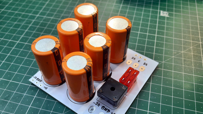
The title “A Simple Linear Power Supply, Done Well” often brings audio projects to mind, and for good reason. Many audio circuits need clean rails and good transient support. A simple transformer, bridge rectifier, and large capacitor bank can provide a strong reservoir for amplifier demand. In dual-rail supplies, positive and negative rails feed op-amps, preamps, and power amplifiers with symmetrical voltage.
However, audio does not automatically require a giant capacitor bank the size of a soda can collection. Bigger capacitors reduce ripple and improve energy storage, but they also increase inrush current, stress rectifiers, and may demand a soft-start circuit. As with seasoning soup, “more” is not always “better.” The right value depends on load current, acceptable ripple, transformer rating, and the rest of the design.
Low-noise audio supplies also benefit from careful transformer selection, proper shielding, clean grounding, and regulator choice. A high-quality linear supply will not fix a bad amplifier layout, but it will avoid adding unnecessary buzz, ripple, or high-frequency hash.
Common Mistakes to Avoid
Choosing Too Much Input Voltage
Extra input voltage becomes regulator heat. Pick the transformer secondary voltage based on dropout margin under worst-case low line, maximum load, ripple valleys, and diode drops. Then check heat at high line and light load.
Ignoring Capacitor Ratings
Capacitors need appropriate voltage, temperature, lifetime, and ripple-current ratings. A capacitor rated for 25 V on a rail that can reach 24 V under light load is living too close to the edge. Electronics should not be designed like a cliffhanger episode.
Underestimating Heat
If a regulator dissipates several watts, calculate junction temperature, use the correct thermal resistance, and test under real load. Finger testing is not engineering, although it is an ancient and painful diagnostic tradition.
Skipping Safety Details
Mains wiring is not the place to improvise. Use proper fuses, strain relief, earth bonding, insulation, creepage distance, and enclosures. Beginners should consider starting with an external certified AC adapter or low-voltage transformer before building anything connected directly to the wall.
When a Linear Supply Is the Right Choice
A linear power supply is a strong choice when low noise, repairability, simplicity, and predictable behavior matter more than size and efficiency. It is especially useful for small analog circuits, low-current instrumentation, audio preamps, development benches, sensor conditioning, and educational projects.
It is usually not the right choice for high-current, battery-powered, compact, or heat-sensitive designs. Dropping 24 V to 5 V at 2 A with a linear regulator is technically possible, but so is wearing a winter coat in a sauna. A switching pre-regulator followed by a linear post-regulator can be a smart hybrid solution: the switcher handles efficiency, and the linear regulator cleans up the final rail.
Experience Notes: What Building Linear Supplies Teaches You
After spending time with linear power supplies, one lesson becomes clear: the schematic is only the beginning. On paper, a supply can look almost insultingly simple. In real life, the transformer hums, the rectifier warms up, the capacitor charges with a thump, the regulator needs more heatsink than expected, and the enclosure suddenly feels smaller than it did when you bought it. That is where the craft begins.
One practical experience is learning to respect transformer voltage. Many first builds use a transformer that seems “close enough,” only to discover that rectified and filtered DC is much higher than expected. A 12 VAC transformer can produce a surprisingly high no-load DC voltage after the bridge and capacitor. The regulator may still output the correct voltage, so the builder celebrates for about three minutes. Then the heatsink becomes too hot to touch, and the celebration turns into thermal math. This is a rite of passage, but it is better as a calculation than as a burn mark.
Another experience is discovering that hum is sneaky. A supply may measure fine with a multimeter, yet still inject audible hum into an amplifier or noise into a sensor circuit. The cause may be grounding, transformer placement, loop area, or high charging currents sharing a return path with sensitive signals. Moving a ground connection by a few centimeters can feel like electronics witchcraft, but it is really current taking the path you accidentally gave it.
Capacitors also teach patience. Large electrolytics can hold charge after power is removed, and they can deliver impressive sparks if shorted carelessly. Adding a bleeder resistor feels boring until the day it prevents a surprise. Likewise, adding a power LED is not just cosmetic; it is a polite warning that the supply is awake.
Testing is where a linear power supply earns trust. A dummy load, thermometer, oscilloscope, and patience reveal more than a quick voltage check ever will. Test at light load, full load, low input, high input, and after the unit has warmed up. Watch ripple. Watch regulator temperature. Listen for transformer buzz. Check whether the enclosure traps heat. A supply that works for five minutes may still fail after an hour in a closed box.
The best experience is the quiet satisfaction of a finished linear PSU that simply behaves. Flip the switch, the rail comes up cleanly, the load runs happily, and nothing complains. No drama, no whining inductor, no mystery resets. Just clean DC, delivered by a circuit that looks simple because the difficult thinking happened before the soldering iron got involved.
Conclusion
A simple linear power supply, done well, is not old-fashioned in the negative sense. It is old-fashioned in the sturdy, readable, repairable sense. It teaches core electronics principles: AC conversion, rectification, filtering, regulation, thermal management, grounding, and safety. It rewards careful design and punishes casual guessing with heat, hum, or blown fuses.
The modern electronics world is full of switching supplies, and most of them deserve their popularity. But when a project needs low noise, simple behavior, and easy troubleshooting, a linear regulated power supply remains a beautiful solution. The secret is not complexity. The secret is respect: respect the transformer, respect heat, respect capacitors, respect grounding, and absolutely respect mains voltage. Do that, and a humble linear PSU can power a project with the quiet confidence of a veteran engineer who owns only one screwdriver but somehow fixes everything.
SEO Tags