
Note: This article is based on real engineering principles, current 3D printing material guidance, plastic gear testing practices, and practical worm gear design considerations.
There is something wonderfully suspicious about a worm gear. It looks like a screw that wandered into a gearbox and somehow got promoted. But give it a matching worm wheel, and suddenly this odd little mechanism becomes one of the most useful ways to turn high-speed rotation into slow, powerful, right-angle motion. Add 3D printing to the mix, and things get even more interesting. Or, depending on your slicer settings, even more melty.
Testing 3D printed worm gears is not just about asking, “Will it spin?” A fidget spinner spins. A sad office chair spins. A worm gear has a tougher job. It must transfer torque, resist wear, survive heat from sliding friction, hold alignment, control backlash, and ideally avoid becoming a tiny pile of plastic confetti under load. For makers, robotics builders, product developers, and anyone who has ever said, “I’ll just print that part,” worm gear testing reveals where desktop manufacturing shinesand where it politely coughs smoke.
What Makes Worm Gears Special?
A worm gear set usually includes a worm, which resembles a threaded shaft, and a worm wheel, which resembles a gear cut to mesh with that thread. The two shafts typically meet at 90 degrees, making worm gears useful when space is tight and direction changes are needed. They are common in actuators, lifts, tuning mechanisms, rotary tables, conveyors, robotics joints, and compact reducers.
The big appeal is reduction ratio. A single-start worm driving a 40-tooth worm wheel creates a 40:1 reduction. That means the input shaft spins 40 times for one wheel revolution. The result is slower output speed and higher torque. In some designs, worm gears can also be self-locking, meaning the wheel cannot easily drive the worm backward. This is valuable for holding loads in place, though it comes with a cost: friction.
And friction is the villain in our 3D printed story. Unlike spur gears, where teeth roll against each other more cleanly, worm gears involve a lot of sliding contact. Sliding produces heat, heat softens many plastics, and softened plastic teeth do not usually file a workplace complaint before failing. They just smear, strip, or seize.
Why Test 3D Printed Worm Gears?
3D printed worm gears can be excellent for prototypes, educational models, light-duty mechanisms, replacement parts, and custom motion systems. They are fast to produce, easy to modify, and cheap enough that testing failures does not require a dramatic budget meeting. But printed gears are not automatically equivalent to machined nylon, injection-molded acetal, bronze, or steel gears.
Testing is essential because 3D printed parts are affected by factors that traditional machined parts do not experience in the same way. Layer direction, extrusion quality, infill pattern, wall count, cooling, nozzle temperature, material moisture, and print orientation all influence strength and wear. A worm gear printed upright may fail differently from the same gear printed flat. A PLA worm wheel may look beautiful on the bench and then behave like warm cheese during a high-speed test.
The Main Variables in a Worm Gear Test
1. Material Choice
The most common FDM materials for testing are PLA, PETG, ABS, ASA, nylon, polycarbonate, and fiber-filled composites. PLA prints cleanly and holds detail well, but it has poor heat resistance compared with engineering plastics. PETG is tougher and less brittle, though it may wear faster under sliding friction. ABS and ASA offer better temperature resistance but require more controlled printing. Nylon is often the best practical choice for moving parts because it is tough, fatigue-resistant, and naturally lower in friction than many hobby materials.
For more demanding applications, SLS nylon or MJF nylon can outperform typical FDM prints because powder-bed processes create more uniform mechanical properties and avoid visible layer seams. Carbon-fiber-filled nylon can add stiffness, but stiffness is not the whole story. A gear tooth also needs fatigue resistance, surface durability, and predictable wear behavior. A very stiff printed part that chips under repeated tooth contact is not a hero; it is just expensive glitter.
2. Print Orientation
Print orientation is one of the most important test variables. FDM parts are anisotropic, meaning their strength changes depending on direction. Layer adhesion is usually weaker than strength along the extruded filament path. For worm gears, that matters because the tooth surface experiences sliding pressure and repeated load cycles.
A worm printed horizontally may have better strength along its shaft but rougher tooth geometry depending on support quality. A worm printed vertically may produce cleaner thread-like geometry but can be weaker between layers. The worm wheel has similar trade-offs. Printing the wheel flat usually produces stronger tooth continuity around the circumference, while printing it upright may expose the teeth to layer-splitting under load.
3. Lubrication
Lubrication is not optional in meaningful worm gear testing. Because worm gears create sliding contact, dry plastic-on-plastic contact heats quickly. A plastic-safe grease can dramatically reduce friction, noise, wear, and temperature rise. PTFE-based grease, silicone grease, and certain white lithium greases may work depending on the plastic, but compatibility matters. Some lubricants can attack certain polymers or collect dust like a tiny mechanical lint roller.
A good test compares dry operation with lubricated operation. The dry test shows the worst-case behavior. The lubricated test shows whether the design has practical potential. If a worm gear survives only when treated like a spa guest, that is still useful data. It means maintenance becomes part of the design.
4. Speed and Load
Speed-only tests are useful but incomplete. Running a gear pair at high RPM with no load can reveal heat buildup, balance issues, alignment problems, and lubrication effects. However, a gear that survives unloaded speed may still fail quickly when asked to move a real load. Torque is where the truth lives.
A better test includes controlled output resistance. This could be a friction brake, a weighted arm, a torque sensor, or a measured load on a lever. The goal is not to torture the part immediately; it is to build a performance map. Test at low speed and light load, then gradually increase one variable at a time. When the gear fails, you want to know whynot just enjoy the dramatic plastic finale.
How to Build a Simple Test Rig
A basic worm gear test rig needs five things: a motor, a secure frame, bearings or bushings, the worm gear pair, and a way to measure results. A DC motor or brushless motor can drive the worm. The worm wheel should be mounted on a shaft with minimal wobble. The center distance between worm and wheel must be adjustable because backlash and tooth contact are critical.
Add a tachometer or encoder to measure input and output speed. Use an infrared thermometer or thermal camera to monitor temperature. If possible, measure current draw from the motor. Rising current can signal friction, binding, or poor alignment. For load testing, attach a lever arm to the output shaft and apply known weights, or use a brake system with a torque sensor.
Keep the frame rigid. A flimsy test rig can make a good gear look bad. Misalignment causes uneven tooth contact, noise, heat, and premature wear. In other words, the gear gets blamed for the test stand’s bad manners.
What to Measure During Testing
Temperature Rise
Temperature is one of the best early warning signs. PLA begins losing stiffness at relatively low temperatures compared with engineering polymers, so even moderate heat can change tooth geometry. Nylon and ABS tolerate heat better, but they are not magic. Record temperature at intervals, especially near the mesh zone.
Backlash
Backlash is the small amount of free movement between mating teeth. Too much backlash produces slop and poor positioning accuracy. Too little backlash creates binding, friction, and heat. Printed gears often need more clearance than machined gears because surface finish and dimensional accuracy are less predictable.
Wear Pattern
After each test, inspect the tooth surfaces. Look for polishing, ridges, pitting, melted areas, powdery debris, tooth root cracks, and uneven contact marks. A healthy gear will show broad, consistent contact. A failing gear may show contact concentrated on one edge, which usually points to misalignment or poor tooth geometry.
Noise and Vibration
Noise is data wearing a funny hat. A smooth worm gear should sound consistent. Grinding, clicking, pulsing, or squealing can indicate rough surfaces, poor lubrication, eccentricity, or tooth interference. Record video and audio during testing so you can compare changes over time.
Efficiency
Worm gear efficiency varies widely because it depends on lead angle, friction, lubrication, materials, load, and geometry. For printed gears, efficiency can be especially sensitive to surface roughness. A rough tooth surface wastes energy as heat. Measuring input power and output torque gives a clearer picture of real performance.
Common Failure Modes
Heat Softening
This is common with PLA and poorly lubricated gear sets. The gear runs smoothly for a moment, then friction raises the temperature, the tooth surface softens, and wear accelerates. Failure may look like smeared or rounded teeth.
Tooth Shear
Under load, the worm wheel teeth may crack or shear. This often happens when tooth roots are too thin, infill is too low, layer direction is unfavorable, or the material is brittle.
Layer Delamination
If the load pulls across weak layer bonds, the part may split. Increasing nozzle temperature, improving enclosure control, changing orientation, and adding perimeters can help.
Abrasive Wear
Some fiber-filled filaments are strong but abrasive. A carbon-fiber-filled worm driving a softer wheel may act like a file. Sometimes the best pairing is not the strongest material against itself, but a harder worm with a tougher, more wear-friendly wheel.
Best Practices for Better 3D Printed Worm Gears
Use generous tooth geometry rather than tiny delicate teeth. Increase face width where possible. Add fillets at tooth roots to reduce stress concentration. Use high wall counts and dense infill, especially around the hub and tooth region. Avoid relying on sparse infill for functional gear teeth.
Design for realistic clearances. FDM printers often need extra backlash because printed surfaces are not perfectly smooth. If the gear binds during hand rotation, it will not magically improve at 3,000 RPM. It will simply fail with more confidence.
Use proper shafts and bearings. A printed shaft running in a printed hole may work for a toy, but serious testing benefits from metal shafts, bushings, or ball bearings. The gear teeth should be the test subject, not a wobbly axle.
Dry nylon filament before printing. Wet nylon can print with bubbles, weak layers, and fuzzy surfaces. For moving parts, surface quality matters. A worm gear tooth is not the place to discover your filament has been drinking humidity like iced tea.
When 3D Printed Worm Gears Make Sense
3D printed worm gears are excellent for concept validation, robotics prototypes, low-speed positioning systems, educational gearboxes, camera sliders, model mechanisms, and custom fixtures. They are especially useful when the design may change several times. Printing five versions in a weekend can teach more than staring at a CAD model for a month.
They are less suitable for high-load, high-speed, safety-critical, or continuous-duty applications unless the material, process, testing, and maintenance plan are carefully engineered. A printed worm gear holding a lightweight camera mount is reasonable. A printed worm gear holding a suspended engine block is a horror story with CAD files.
Practical Testing Example
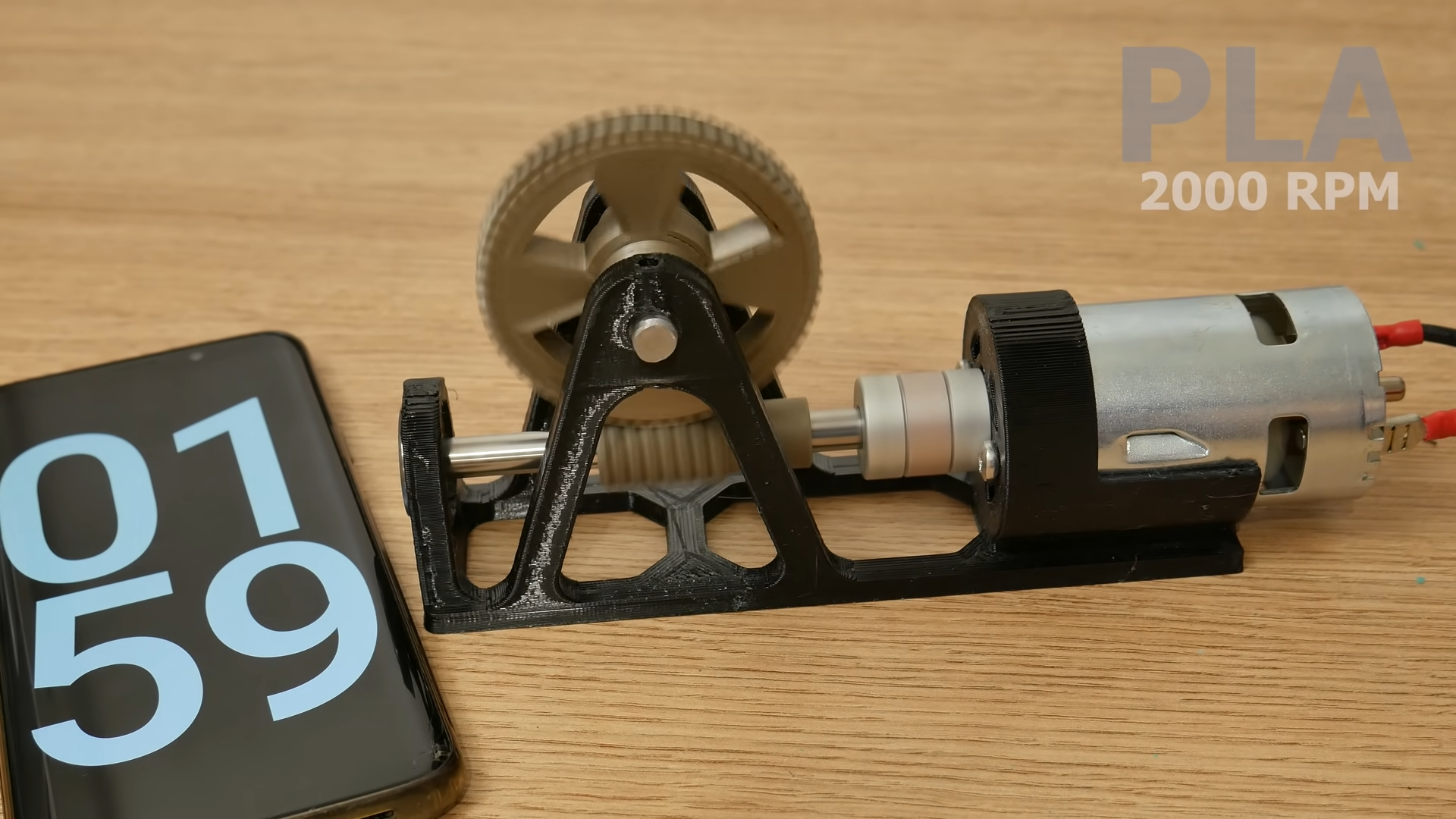
Imagine testing three worm wheel materials: PLA, PETG, and nylon. Each wheel has the same tooth count and geometry. The worm is printed in nylon, the shaft is steel, and the frame uses bearings. First, run each gear set dry at low speed for five minutes. Record temperature, noise, and wear. Then repeat with plastic-safe grease. Finally, apply a measured output load and run each material at increasing speeds.
The likely result is that dry PLA heats quickly and wears fastest. PETG may survive better but show surface deformation or stringy wear. Nylon will probably perform best under repeated sliding contact, especially when lubricated. However, nylon may also print less accurately if moisture control and printer setup are poor. The winner is not just the material on the spool; it is the entire process.
Experience Notes: Lessons From Testing 3D Printed Worm Gears
The first lesson is that a worm gear can look perfect and still perform terribly. Visual inspection is useful, but tooth contact tells the real story. A shiny, accurate-looking worm may have tiny layer ridges that create heat under sliding load. A wheel may measure correctly across its diameter but still have tooth profiles that bind because the slicer approximated curves too aggressively.
The second lesson is that lubrication changes everything. Running plastic worm gears dry is like running a marathon in sandpaper socks. It may technically begin, but nobody involved is having a good time. In many workshop tests, the difference between dry and lubricated operation is the difference between rapid failure and surprisingly stable performance. Grease reduces friction, quiets the mesh, and helps distribute heat. Still, too much grease can attract debris, so a thin, even application is better than packing the gearbox like a peanut butter sandwich.
The third lesson is that alignment deserves more respect than it gets. Many failed printed gear tests are not really material failures. They are assembly failures wearing a disguise. If the worm sits slightly too high, too low, or at a poor center distance, the tooth load concentrates in a small area. That creates heat, noise, and rapid wear. Adjustable mounts make testing much easier. Start with a small amount of backlash, rotate by hand, listen and feel for tight spots, then run at low speed before increasing RPM.
The fourth lesson is that print settings should be treated like engineering inputs, not decorative preferences. More perimeters often help more than simply raising infill. A gear tooth loaded near the surface benefits from strong outer walls. Layer height affects tooth smoothness. Nozzle diameter affects detail. Cooling settings affect strength and accuracy. For small worm gears, a finer layer height can improve tooth contact, but slower print time is the entry fee.
The fifth lesson is to test in stages. Do not start with maximum speed and maximum load unless your goal is entertainment. Begin with hand rotation. Then run slowly without load. Then add lubrication. Then add moderate speed. Then apply load. This staged process reveals the failure threshold and gives useful data. A catastrophic failure at full speed tells you the design failed. A careful step-by-step test tells you when and why.
The sixth lesson is that replacement is part of the design. Printed worm gears may be perfectly acceptable as consumable components in light-duty machines. If a wheel costs less than a cup of coffee and takes 40 minutes to print, planned replacement may be smarter than overengineering. For a prototype, this is a strength, not a weakness. The goal is learning quickly, iterating cheaply, and saving machined parts for the version that earns them.
Finally, keep notes. Record material brand, print orientation, nozzle size, temperature, infill, wall count, lubrication type, load, speed, runtime, and failure mode. After five tests, memory becomes unreliable. After ten tests, memory becomes fan fiction. Good notes turn broken parts into engineering progress.
Conclusion
Testing 3D printed worm gears is a practical way to understand the limits of printed mechanical parts. Worm gears are compact, powerful, and useful, but they are also demanding because sliding friction creates heat and wear. Material selection, print orientation, lubrication, backlash, alignment, and load all determine whether a printed worm gear becomes a functional mechanism or a small plastic lesson.
For light-duty projects, prototypes, and experimental machines, 3D printed worm gears can work impressively well when designed and tested carefully. For high-load or long-running systems, they require serious validation and may need engineering materials such as nylon, SLS nylon, or hybrid designs using metal worms and printed wheels. The best approach is simple: print, test, measure, improve, and repeat. The worm gear may be humble, but it has plenty to teach.
SEO Tags