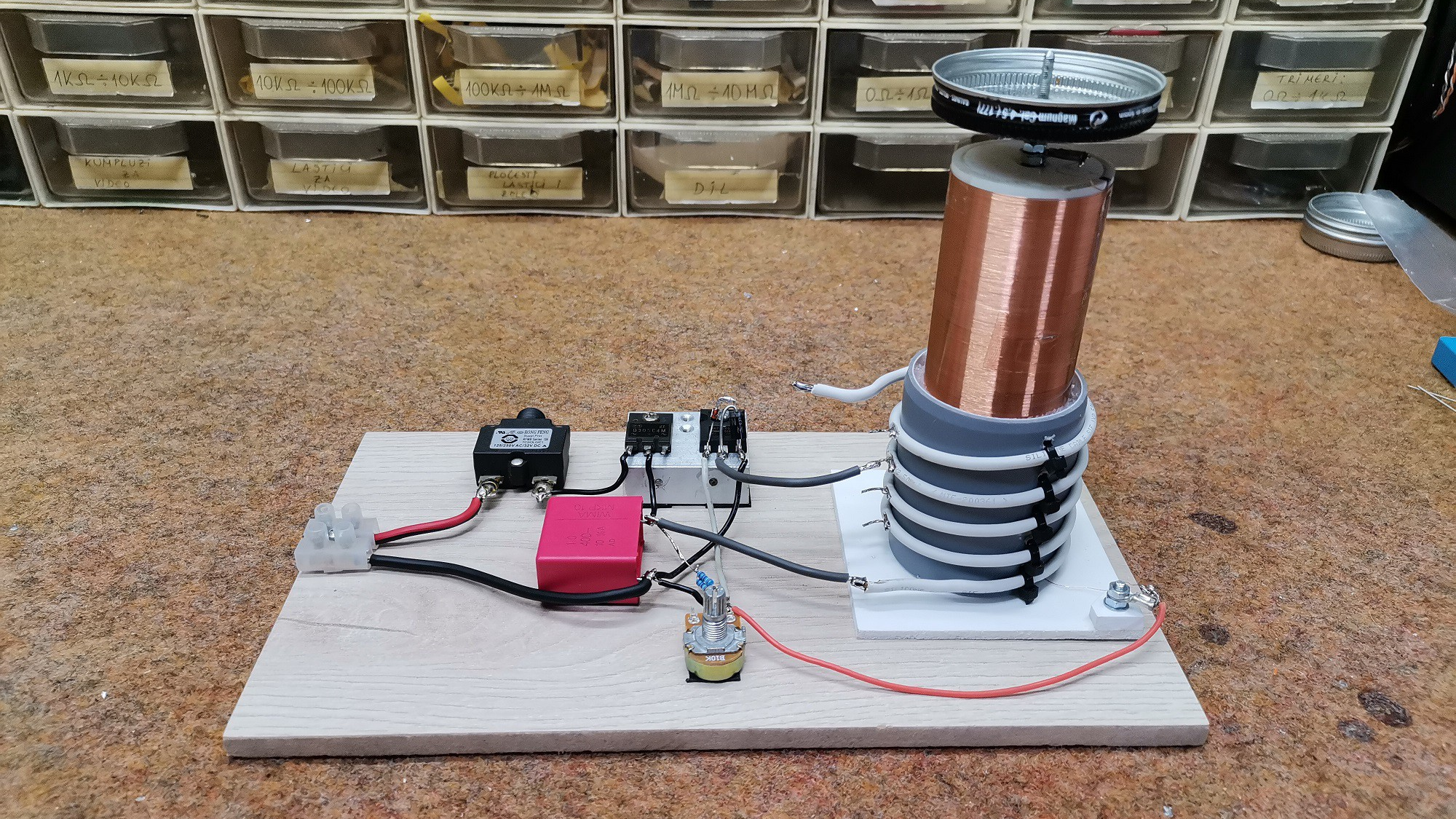

A single transistor solid state Tesla coil sounds like something invented by a sleep-deprived wizard with a soldering iron and a questionable relationship with safety goggles. Yet the idea is wonderfully real: using one switching device, usually a MOSFET or bipolar transistor, to drive a resonant coil and produce high-voltage, high-frequency effects. No spark gap clacking like an angry typewriter. No giant oil-filled transformer sulking in the corner. Just a compact circuit, a carefully wound secondary coil, a few supporting parts, and enough electrical drama to make a fluorescent tube glow from across the bench.
At its heart, a Tesla coil is a resonant transformer. It uses magnetic coupling and resonance to turn comparatively low input voltage into very high voltage at radio frequency. Traditional spark-gap Tesla coils do this with a capacitor, a primary coil, and a spark gap that fires in pulses. A solid state Tesla coil, or SSTC, replaces the spark gap with semiconductor switching. A single-transistor SSTC goes even further by stripping the driver down to one main power switch. That simplicity is the charmand also the trap. The circuit may look small, but it deals with fast edges, inductive kickback, heat, radio-frequency interference, and voltages that do not care about your weekend plans.
What Is a Single Transistor Solid State Tesla Coil?
A single transistor solid state Tesla coil is a compact Tesla coil design in which one active switching device energizes the primary winding or base of the resonator. The transistor rapidly turns current on and off, feeding energy into the coil at or near its resonant frequency. The secondary coil, usually made with hundreds or thousands of turns of fine magnet wire, resonates with its own capacitance and any top load attached to it. When tuned correctly, voltage builds at the top terminal until it produces corona, streamers, or enough electric field to light nearby gas-filled lamps.
Many hobbyists know the simplest version as a “Slayer exciter,” a self-oscillating circuit often built with one transistor, a primary coil, a secondary coil, and a feedback winding or antenna-like pickup. More advanced versions use a MOSFET, a gate driver, and an oscillator to form a single-switch Class E solid state Tesla coil. Both families share the same basic theme: one semiconductor does the heavy lifting while the resonator performs the magic trick. The difference is that Class E designs demand tighter tuning and better switching behavior, while basic self-oscillating circuits are more forgiving but generally less powerful and less efficient.
How the Tesla Coil Principle Works
Resonance: The Secret Sauce
Resonance is the reason a Tesla coil can do so much with what appears to be so little. Imagine pushing a child on a swing. Push at random times and you mostly look confused. Push at the right moment and the swing climbs higher with each pass. A Tesla coil works in a similar way, except the swing is an electromagnetic field and the playground supervisor is probably asking why your hair is standing up.
The secondary coil acts as an inductor. Its windings, nearby objects, the surrounding air, and the top load create capacitance. Together they form an LC resonant circuit. When the driver feeds energy at the right frequency, voltage rises dramatically at the top of the secondary. A metal sphere, toroid, or even a smooth can may be used as a top load because it adds capacitance and helps control where corona begins.
Primary and Secondary Coupling
The primary coil usually has only a few turns of thicker wire because it carries relatively high current. The secondary has many turns of fine wire because it develops high voltage but comparatively low current. In a small single-transistor Tesla coil, the primary might be only a handful of turns wrapped near the base of the secondary. In larger or more refined solid state builds, spacing, coupling, and coil geometry become serious design concerns. Too little coupling wastes energy. Too much coupling can cause unstable operation, racing sparks along the secondary, or semiconductor failure. In other words, the coil is not just a tube with wire on it; it is a musical instrument for electrons, and it goes out of tune easily.
Why Use One Transistor?
The most obvious advantage is simplicity. A full-bridge or half-bridge SSTC can deliver impressive power, but it requires multiple switches, gate-drive circuitry, dead-time control, careful layout, and often current limiting. A single-transistor design reduces the main power stage to one device. That makes the project cheaper, smaller, and easier to understand. For students and electronics enthusiasts, it is a fantastic introduction to switching, resonance, feedback, MOSFET behavior, coil winding, and the unpleasant smell of a component that has decided to become smoke.
Another benefit is visibility. In a simple single-transistor circuit, cause and effect are easier to observe. Change the top load and the resonant frequency shifts. Move the primary and output changes. Improve the gate drive and the transistor runs cooler. Use a slow diode where an ultrafast diode is needed and performance falls apart. The circuit becomes a practical classroom where the tuition is paid in patience and occasionally a replacement MOSFET.
Common Circuit Styles
The Self-Oscillating Slayer Exciter
The Slayer exciter is the friendly gateway creature of the Tesla coil world. It often uses a bipolar transistor or MOSFET, a primary winding, a secondary winding, and feedback from the secondary to keep the transistor switching at a frequency related to the coil’s resonance. Because the circuit follows the resonator to some degree, it can be easier to get working than a manually tuned oscillator. It is popular for lighting fluorescent lamps wirelessly, demonstrating electric fields, and making tiny corona effects.
However, the Slayer exciter is not a precision power converter. The transistor may switch inefficiently, the waveform can be rough, and the circuit may become unstable as the spark load changes. It is best treated as an educational low-power experiment, not as a shortcut to monster arcs.
The Single-MOSFET Class E SSTC
A Class E solid state Tesla coil is a more refined single-switch design. Instead of simply hammering the primary, the circuit shapes voltage and current so the MOSFET switches under more favorable conditions. In a well-tuned Class E amplifier, the switch ideally turns on when voltage across it is low, reducing switching loss. That is the theory. In practice, the layout, gate drive, drain voltage, primary inductance, shunt capacitance, top load, and operating frequency all matter. A Class E Tesla coil can be efficient and elegant, but it is less tolerant of guesswork than the humble Slayer exciter.
Some documented hobbyist versions use an adjustable oscillator, a MOSFET gate driver, an ultrafast diode, and a carefully selected MOSFET. Frequencies may range from hundreds of kilohertz to several megahertz depending on the coil geometry. At these speeds, “close enough” is not always close enough. A transistor that looks powerful on paper may fail quickly if it has excessive gate charge, slow switching, inadequate voltage rating, or poor thermal management.
Key Parts of the Build
The Transistor
The transistor is the star of the show and the first part likely to complain. For small circuits, a bipolar transistor such as a 2N2222 or BD243 may appear in simple educational builds. For higher power, builders commonly use MOSFETs because they can switch large currents quickly with proper gate drive. Important specifications include drain-source voltage rating, current rating, total gate charge, on-resistance, switching speed, avalanche ruggedness, and package thermal resistance. A big current rating alone does not guarantee success. At radio frequencies, a slow “muscle” transistor can lose to a faster, better-driven device.
The Gate or Base Drive
A MOSFET gate behaves partly like a capacitor. It must be charged and discharged every switching cycle. At several hundred kilohertz or higher, weak drive causes slow transitions, heat, and efficiency loss. This is why many serious single-MOSFET SSTC designs use a dedicated gate-driver IC rather than connecting a logic signal directly to the gate. Gate resistors, Zener clamps, and compact layout help control ringing and protect the device from voltage spikes.
The Primary Coil
The primary coil is usually made from thicker wire, copper tubing, or insulated copper wire. It may have only a few turns in low-voltage builds or more turns in certain Class E designs. Its job is to couple energy into the secondary without overheating or creating unwanted arcs. The primary should be mechanically secure, kept away from the high-voltage top end of the secondary, and adjusted with care. A loose primary lead flopping around a Tesla coil is not “experimental freedom”; it is a tiny lightning invitation.
The Secondary Coil
The secondary coil is where patience becomes visible. Fine magnet wire is wound in a single layer on a nonconductive tube, often PVC or acrylic. Smooth, even winding improves performance and reduces weak spots. The secondary may contain several hundred to more than a thousand turns depending on the desired frequency and size. Many builders seal the winding with varnish, polyurethane, or epoxy to protect it from moisture, scratches, and corona damage.
The Top Load
The top load adds capacitance and shapes the electric field. A smooth toroid is preferred in many Tesla coil designs because it reduces premature breakout from sharp points. Small coils may use a metal sphere, aluminum ducting toroid, or rounded metal can. Increasing the top load generally lowers the resonant frequency. That can improve streamers, but it also changes tuning. The top load is not decoration; it is an active part of the resonant circuit wearing a shiny hat.
Tuning a Single Transistor SSTC
Tuning is the difference between a lively coil and a hot transistor quietly reconsidering its career. The goal is to drive the secondary at or near resonance while keeping the switch within safe voltage, current, and temperature limits. With test equipment, builders use an oscilloscope, signal generator, current probe, or frequency counter to observe resonance and switching behavior. Without professional tools, small low-power demonstrations sometimes use a neon bulb or compact fluorescent lamp near the coil as a crude resonance indicator. The brightest glow often appears near resonance, though this method is approximate and should not be used as a substitute for safe measurement in higher-power circuits.
In adjustable oscillator designs, the frequency is swept slowly while input voltage is kept low. The builder watches for maximum output, minimum transistor heating, and stable operation. In primary-tuned systems, the number of active primary turns may be changed. In top-load tuning, adding or removing capacitance shifts the secondary frequency. Every adjustment interacts with the others. Tesla coil tuning is less like setting a kitchen timer and more like persuading a cat to sit on a specific cushion.
Performance Expectations
A small single-transistor Tesla coil may light fluorescent tubes, create a purple corona brush, or produce short streamers. A more developed single-MOSFET Class E coil can produce longer sparks, especially with adequate input power and careful tuning. Still, it should not be compared directly with large half-bridge, full-bridge, or double-resonant solid state Tesla coils. Those designs can process far more power and generate much larger discharges.
The beauty of a single-transistor SSTC is not that it wins every spark-length contest. Its value is that it makes the core physics visible with a minimal circuit. You can see resonance, coupling, switching loss, electromagnetic interference, insulation limits, and thermal management all in one tabletop project. It is a compact laboratory disguised as a lightning toy.
Safety: The Section That Keeps You Owning Eyebrows
A Tesla coil is not harmless just because the current is high frequency. High voltage can cause burns, startle reactions, damaged electronics, insulation breakdown, ozone production, and electromagnetic interference. People with pacemakers, implanted medical devices, or sensitive equipment should stay well away. Never operate a Tesla coil near flammable vapors, fuel, aerosols, loose metal objects, or expensive electronics unless your hobby is apologizing.
Capacitors can remain charged after power is removed. Power supplies can deliver dangerous current. RF arcs can burn skin. Grounding mistakes can put hazardous voltage where it does not belong. A proper build uses current limiting, fusing, insulated controls, physical barriers, one-hand measurement habits, discharge resistors, and a clear emergency shutoff. Beginners should start with low voltage, battery-powered experiments and learn measurement skills before attempting higher power. The goal is to make sparks in the air, not in your nervous system.
Common Mistakes and How to Avoid Them
Using the Wrong Transistor
A transistor with a huge current rating may still be unsuitable if it switches slowly or has high gate charge. Choose devices intended for fast switching and provide a proper gate drive. Heat sinking is not optional at higher power. If the transistor gets hot quickly at low output, the circuit is mistuned or the drive is poor.
Ignoring Layout
At high frequency, wires become inductors, traces become antennas, and breadboards become tiny chaos farms. Keep high-current loops short. Place gate-driver components close to the MOSFET. Use good decoupling capacitors near the driver and power stage. Avoid long, wandering ground paths.
Overdriving Too Early
Many failures happen because the builder applies full voltage before confirming oscillation, tuning, and waveform quality. Start low. Increase power slowly. Watch current draw. Check temperature. Listen for abnormal buzzing. A Tesla coil usually gives warnings before it destroys something; unfortunately, those warnings are sometimes measured in milliseconds.
Forgetting Electromagnetic Interference
Tesla coils are radio-frequency noise machines. They can disrupt nearby computers, radios, microcontrollers, touch screens, and audio equipment. Keep sensitive electronics away, use short leads, add filtering where appropriate, and avoid operating near communication equipment. The coil may be small, but its electromagnetic personality is not shy.
Practical Uses and Educational Value
A single transistor solid state Tesla coil is mainly an educational and demonstration device. It can show wireless energy transfer, gas discharge, corona effects, resonance, electromagnetic fields, and switching electronics. It can light fluorescent tubes without direct contact and create visible streamers from a small top load. In classrooms, maker spaces, and home labs, it offers a memorable way to connect theory with physical behavior.
It also teaches humility. Textbook circuits live in a peaceful world where wires have no inductance and components obey politely. Tesla coils live in the real world, where parasitics throw confetti into your calculations. That makes them challenging, but also deeply rewarding. When the lamp glows near the coil for the first time, the lesson sticks better than a paragraph in a physics book.
Experience Notes: What Building One Teaches in Real Life
Practical experience with single-transistor solid state Tesla coils tends to follow a familiar emotional arc: confidence, confusion, cautious success, overconfidence, smoke, and then genuine learning. The circuit diagram may look almost too simple. A few turns here, many turns there, a transistor in the middlehow hard could it be? Then the real world arrives wearing steel-toed boots.
The first lesson is that coil winding matters more than beginners expect. A secondary coil with uneven turns, scraped enamel, or dusty gaps may still work, but it will not work gracefully. Smooth winding improves insulation and reduces unwanted corona points. Builders often discover that rushing the secondary saves one hour at the beginning and costs three evenings later. The coil is the body of the project; treat it like furniture, not scrap wire.
The second lesson is that tuning is alive. A circuit that behaves perfectly with no top load may change completely when a metal sphere is added. A coil that produces a faint corona at one frequency may suddenly light a fluorescent tube when the oscillator is moved slightly. Bringing a hand, tool, lamp, or grounded object near the top load changes the capacitance and therefore the resonant behavior. This is why experienced builders avoid assuming that calculated frequency is the final truth. Calculations get you into the neighborhood; measurements knock on the correct door.
The third lesson is thermal honesty. Transistors do not negotiate. If the MOSFET is heating rapidly, something is wrong: poor gate drive, excessive current, mistuning, inadequate heat sinking, bad layout, or all of the above having a group meeting. A warm transistor may be acceptable. A transistor that becomes too hot to touch within seconds is not “powerful”; it is resigning. Lower the input voltage, improve the drive, verify frequency, and check the waveform before trying again.
The fourth lesson is that small coils still create big interference. A nearby speaker may buzz. A touch lamp may behave like it has seen a ghost. A microcontroller board on the same bench may reset. This is not supernatural activity; it is radio-frequency energy coupling into places it was not invited. Good bench discipline helps: keep the work area clear, separate the coil from laptops and phones, and use battery power or filtered supplies for experiments when possible.
The fifth lesson is emotional: success with a single-transistor SSTC feels wonderfully disproportionate. The parts count is low, the circuit is compact, and yet the result looks like bottled science fiction. A fluorescent tube glowing in open air never gets old. A purple corona hissing from a smooth terminal is the kind of thing that makes visitors say, “Is that safe?”which is your cue to say, “Not if we get careless,” and then demonstrate proper distance, barriers, and shutdown procedure.
In the end, a single transistor solid state Tesla coil is valuable because it compresses a large amount of electrical engineering into a small, dramatic project. It teaches resonance, switching, feedback, grounding, layout, insulation, thermal design, and respect for high voltage. It is not the biggest Tesla coil, nor the loudest, nor the most powerful. But as a learning machine, it is hard to beat. It is simple enough to understand, complex enough to challenge, and flashy enough to remind you why electronics is fun in the first place.
Conclusion
A single transistor solid state Tesla coil is one of the most fascinating small high-voltage projects in electronics. It combines the elegance of resonance with the practicality of semiconductor switching, giving hobbyists a compact way to explore Tesla coil behavior without building a traditional spark-gap monster. The design can be as simple as a self-oscillating exciter or as refined as a single-MOSFET Class E driver. Either way, success depends on tuning, safe construction, suitable components, careful layout, and respect for the invisible forces involved.
For learners, the project is more than a spark generator. It is a hands-on introduction to LC circuits, RF energy, transistor switching, magnetic coupling, and real-world circuit behavior. Build it carefully, operate it responsibly, and it becomes a brilliant educational tool. Treat it casually, and it becomes an expensive lesson with smoke effects. Fortunately, when approached with patience and safety, this small coil can deliver a big reward: visible electricity, practical knowledge, and the satisfying feeling that you have convinced physics to put on a tiny lightning show.