
Software-defined radio has a funny way of making invisible things feel almost touchable. One minute, radio frequency energy is just a mysterious wave floating through the room. The next minute, an SDR waterfall display turns it into colorful streaks, humps, and suspicious little blobs that look like they are trying to escape a science fair poster. Among the most useful rabbit holes in this world is the study of IF, or intermediate frequency. That is where many SDR IF experiments begin.
In simple terms, an intermediate frequency is a frequency used between the original radio frequency signal and the final baseband signal that software can analyze, filter, demodulate, and display. Traditional radios have used IF stages for decades because it is often easier to filter and amplify a signal after it has been shifted to a more convenient frequency. Modern software-defined radio keeps the same basic idea but moves more of the work into digital processing. That is where things get exciting: instead of swapping coils, crystals, and filter cans, you can change settings, sample rates, filter bandwidths, and decimation values with software.
SDR IF experiments are valuable because they reveal what is really happening inside a receiver. They show how tuner chips, ADCs, digital filters, and software blocks work together. They also teach a humbling lesson: the spectrum display does not always show “the truth.” It shows the truth after hardware limits, sampling choices, aliasing, gain settings, and filters have all had their say. In other words, the waterfall is honest, but it has a complicated personality.
What Is IF in Software-Defined Radio?
IF stands for intermediate frequency. In a receiver, the antenna picks up a radio frequency signal. That signal may be at 100 MHz for FM broadcast, 162 MHz for NOAA weather radio, 433 MHz for low-power devices, or somewhere else entirely. Instead of processing that high-frequency signal directly, many receivers mix it with a local oscillator to shift it down to a lower frequency. That lower frequency is the IF.
Why bother? Because signal processing becomes easier when the target signal sits in a predictable place. Filters can be designed around a fixed or narrow range. Amplifiers can be optimized. Analog-to-digital converters can sample a signal more practically. The receiver can also reject unwanted signals before they overwhelm later stages.
In SDR systems, IF may be analog, digital, or both. Some receivers digitize an IF signal and then use digital downconversion to shift it to baseband. Others use direct-conversion or zero-IF architecture, where the signal is mixed directly down to I/Q baseband near zero frequency. Both approaches have advantages. IF sampling can offer strong selectivity and familiar filtering behavior. Zero-IF designs can reduce hardware complexity and make wideband tuning more flexible. Neither is magic. Each has trade-offs, and experiments help expose them.
Why SDR IF Experiments Matter
Many beginners start SDR by plugging in a USB dongle, launching SDR software, and hunting for strong signals. That is a great first step, but IF experiments go deeper. They answer questions like: What happens when the IF filter is too wide? What does aliasing look like? Why does a signal appear mirrored? How does sample rate affect what lands in the display? Why does changing gain sometimes make reception worse instead of better?
These questions matter because SDR is not only about receiving radio. It is about understanding measurement. An SDR is a receiver, a spectrum analyzer, a recorder, and a DSP lab squeezed into one setup. When you experiment with IF settings, you are learning how radio hardware and digital signal processing shake hands. Sometimes they shake hands politely. Sometimes they slap each other with spurious signals and call it a day.
The Basic SDR IF Signal Chain
A common SDR receive chain begins with an antenna, followed by filtering, low-noise amplification, frequency conversion, analog-to-digital conversion, and digital processing. The exact layout depends on the device. A low-cost RTL-SDR dongle, an Airspy receiver, an SDRplay unit, and a USRP device do not all behave the same way. Still, the core ideas are similar.
1. Antenna and Front-End Filtering
The antenna collects everything it can. Unfortunately, it is not polite enough to collect only the signal you want. Strong local broadcast stations, nearby transmitters, switching power supply noise, and random RF clutter can all enter the receiver. Front-end filtering helps reduce unwanted energy before it causes trouble.
2. Mixer and Local Oscillator
The mixer combines the incoming signal with a local oscillator. This creates sum and difference frequencies. The receiver chooses the useful product and rejects the rest. In an IF receiver, the desired signal is translated to an intermediate frequency. In zero-IF, the signal is translated directly near DC as I and Q components.
3. IF Filtering
The IF filter controls how much spectrum passes through. A narrow IF bandwidth can reduce noise and nearby interference, but it may distort or clip wider signals. A wide IF bandwidth can preserve more signal detail, but it lets more unwanted energy through. SDR IF experiments often focus on this trade-off because it is easy to see on a spectrum display.
4. ADC Sampling
The analog-to-digital converter turns the signal into samples. Sample rate, resolution, clock quality, and input level all matter. If the sample rate is not chosen carefully, aliases can appear. If the ADC is overloaded, the display may show false signals that were created by the receiver itself. That is the radio equivalent of blaming ghosts for a mess you made with the gain slider.
5. Digital Downconversion and DSP
After digitization, software or FPGA logic can shift, filter, decimate, demodulate, and visualize the signal. GNU Radio, SDR#, GQRX, CubicSDR, MATLAB, Python, and other tools can all be used for SDR IF analysis. GNU Radio is especially useful because its block-based flowgraphs make it possible to build a receiver piece by piece.
A Real-World Example: R820T IF Experiments
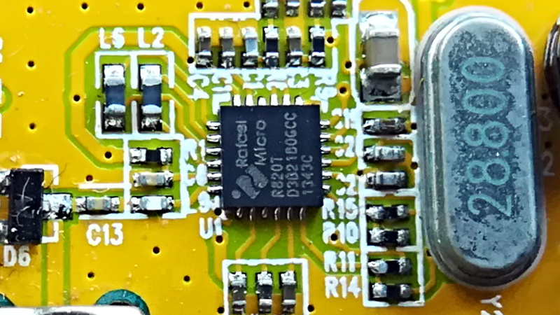
One well-known SDR IF experiment explored the R820T tuner chip, which has been used in popular RTL-SDR-style dongles and related receivers. The experiment looked at how IF configuration registers affected the output when the tuner received a noise source. That may sound boring until you realize that noise is a fantastic test signal. It spreads energy across a wide range, making filter shapes and bandwidth limits easier to see.
The experiment focused on adjustable IF-related settings, including coarse IF filter bandwidth, fine bandwidth tuning, and high-pass filter behavior. By capturing samples and visualizing the result, the experiment showed how each register setting shaped the output. Some settings produced useful passbands. Others created confusing results because of aliasing at the chosen sample rate. That is exactly why IF experiments are useful: they turn hidden chip behavior into visible evidence.
For hobbyists, the big takeaway is not “memorize every register value.” The real lesson is that SDR hardware has personality. A tuner chip is not a perfect theoretical block. It has filters, gain stages, mixers, limits, and quirks. When you understand those quirks, your receiver becomes less of a black box and more of a lab partner. A slightly moody lab partner, yes, but still helpful.
Common SDR IF Experiments You Can Try
Safe, receive-only experiments are the best way to learn. Always follow local radio laws, avoid transmitting without authorization, and focus on public signals such as broadcast FM, weather radio, amateur radio beacons, or test signals from approved lab equipment.
Experiment 1: Observe IF Bandwidth Changes
Tune to a strong, legal public signal and adjust the receiver bandwidth. Watch the spectrum and waterfall. With a wider bandwidth, you may see more surrounding noise and adjacent-channel energy. With a narrower bandwidth, the signal may become cleaner, but audio or data quality can suffer if the filter cuts into the useful modulation.
This experiment teaches one of the most important SDR habits: bandwidth should match the signal. Narrowband FM does not need the same filter width as broadcast FM. AM voice does not need the same bandwidth as a wide digital waveform. A filter that is too generous invites noise to the party. A filter that is too strict throws part of the guest of honor out the window.
Experiment 2: Change Sample Rate and Watch Aliasing
Sample rate determines how much spectrum the SDR can represent. If signals or noise land outside the usable sampled range, they can fold back as aliases. Aliasing can make signals appear where they do not really exist. By changing sample rates and observing which features move, disappear, or mirror, you can learn to distinguish real signals from sampling artifacts.
This is one of the most eye-opening SDR IF experiments because it challenges trust in the display. A beginner may assume every spike is a real transmitter. A more experienced operator asks: Is this signal real, or did my sample rate and filtering create a costume party?
Experiment 3: Compare Real Sampling and I/Q Sampling
Some SDR workflows use real-valued samples, while others use complex I/Q samples. I/Q sampling preserves phase information and allows signals above and below the tuned center frequency to be represented separately. Real sampling can produce mirrored images because positive and negative frequency components overlap in interpretation.
By comparing real and complex sampling modes, you can see why I/Q data is so important in modern SDR. It allows cleaner frequency translation, better demodulation, and more flexible digital filtering. It also explains why I and Q imbalance can produce image artifacts that look like weak duplicate signals.
Experiment 4: Build a Frequency-Translating Filter
A frequency-translating FIR filter shifts a selected slice of spectrum while filtering and decimating it. This is a classic SDR technique. Instead of processing an entire wideband capture, you select the channel you care about, move it to baseband, reduce the sample rate, and then demodulate it.
In GNU Radio, this type of block is useful for turning a messy wideband input into a manageable narrowband stream. The experiment helps connect three ideas at once: frequency translation, filtering, and sample-rate reduction. Once that clicks, many SDR receiver designs suddenly feel less mysterious.
Experiment 5: Record IF Data and Analyze It Later
Live SDR work is exciting, but recorded samples are better for careful analysis. Record a short IF or I/Q sample file from a known signal, then replay it through different filters and demodulators. Because the original data stays the same, you can compare settings fairly. This is especially helpful when testing filter taps, decimation ratios, and demodulation choices.
Recorded IF data also makes troubleshooting less frantic. Instead of chasing a signal that fades, drifts, or vanishes, you can replay the same capture repeatedly. It is like putting the radio signal in a jar, except the jar is a file and the signal does not complain.
Important Concepts Behind SDR IF Experiments
Nyquist and Sampling
The Nyquist-Shannon sampling theorem explains the relationship between sample rate and signal bandwidth. In practical SDR work, the key idea is simple: the sample rate must be high enough to represent the bandwidth you want, and filtering must prevent unwanted frequencies from folding into the band of interest.
Decimation
Decimation reduces sample rate after filtering. This is not just a convenience; it is a performance strategy. Processing fewer samples lowers CPU load and makes narrowband demodulation more efficient. However, decimation without proper filtering can cause aliasing. The correct order is filter first, decimate second. Your CPU will thank you, and your spectrum display will stop hallucinating as much.
Dynamic Range
Dynamic range describes how well a receiver handles weak and strong signals at the same time. A receiver with limited dynamic range may struggle when a strong local signal sits near a weak target. IF filtering and gain control help, but they cannot fix every front-end overload problem. Sometimes the best solution is an external filter or attenuator.
Frequency Planning
IF frequency planning means choosing intermediate frequencies that avoid images, spurs, aliases, and filter conflicts. In high-performance receivers, this is serious engineering. In hobby SDR experiments, it is still worth understanding. If a strange signal appears, think through the mixing products and sampling zones before declaring that you have discovered alien Wi-Fi.
Best Tools for SDR IF Experiments
A low-cost RTL-SDR dongle is enough for basic experiments, especially with strong public signals. An Airspy, SDRplay, HackRF, LimeSDR, or USRP offers more bandwidth, better performance, or transmit capability depending on the model. For beginners, receive-only work is the safest and simplest path. Transmitting requires proper authorization, correct filtering, and serious attention to regulations.
For software, GNU Radio is one of the most powerful choices because it allows you to build complete signal chains visually. SDR# is friendly for quick listening and spectrum observation. GQRX is useful on Linux and macOS. Inspectrum is excellent for inspecting recorded signals. Python with NumPy and SciPy is great for offline analysis, especially when you want to calculate FFTs, plot spectra, or test filter behavior.
Common Mistakes in SDR IF Experiments
The first mistake is using too much gain. More gain does not always mean better reception. If the front end overloads, the SDR may create false signals through distortion. The second mistake is ignoring sample rate. A display that looks wide and impressive may be full of aliases if the signal chain is not configured properly. The third mistake is assuming the antenna is innocent. A poor antenna can make good hardware look terrible, while a strong local signal can make a good antenna look like it is trying too hard.
Another common mistake is testing with unknown signals. Known signals make better experiments because you can compare expected behavior with observed behavior. Broadcast FM, weather radio, lab signal generators, or amateur radio beacons are useful references. Mystery signals are fun, but they are not always good teachers.
Practical Experiences with SDR IF Experiments
The best SDR IF experiments usually begin with a boring setup. That sounds disappointing, but boring is beautiful in engineering. A stable antenna, a known signal, a fixed gain setting, and a repeatable sample rate will teach more than a chaotic setup full of moving variables. When I approach an SDR IF test, I treat it like a cooking recipe where one ingredient changes at a time. Change the bandwidth, observe. Change the sample rate, observe. Change the frequency offset, observe. If everything changes at once, the result may look scientific, but it is really just soup with a USB cable.
One practical lesson is that the waterfall display is more useful when you slow down and watch patterns over time. A real signal often has structure: a carrier, sidebands, bursts, fading, or modulation shape. An alias may move strangely when the sample rate changes. An overload product may appear only when gain is high. A filter edge may show up as a sudden cliff in the noise floor. These clues turn SDR from “look at the pretty colors” into actual investigation.
Another experience worth sharing is that narrow filters feel magical until they are too narrow. When listening to voice or data, a tight filter can reduce noise dramatically. But if it cuts into the modulation, the recovered signal becomes muffled, distorted, or unreliable. The trick is not to chase the smallest bandwidth number. The trick is to fit the filter to the signal like a good pair of shoes. Too wide, and you drag in mud. Too tight, and nobody enjoys the walk.
Gain control is another area where beginners often learn the hard way. It is tempting to push gain up because weak signals get taller on the display. But if the noise floor rises with everything else, nothing really improved. Worse, overload can create phantom signals. A better approach is to start low, raise gain gradually, and watch whether the signal-to-noise ratio improves. If the whole spectrum rises together, you may be amplifying noise. If new spikes appear everywhere, the receiver may be protesting.
Recorded samples are a secret weapon. A short capture lets you test the same signal with different filters, FFT sizes, demodulators, and decimation settings. This makes learning faster because the signal is no longer changing while you think. It also makes note-taking easier. Keep a simple log: device, antenna, center frequency, sample rate, gain, filter bandwidth, and what changed. After a few sessions, patterns emerge. You begin to recognize overload, aliasing, images, DC spikes, and filter roll-off without needing a dramatic “aha” moment.
Finally, SDR IF experiments reward patience. The first session may feel like trying to read a map drawn by a caffeinated robot. But after enough careful tests, the display starts to make sense. You see how IF bandwidth shapes noise, how sample rate frames the spectrum, how frequency translation isolates a channel, and how digital filtering turns raw samples into useful information. That is the real charm of SDR: it turns radio into a workshop where every knob is also a lesson.
Conclusion
SDR IF experiments are one of the most practical ways to understand software-defined radio beyond the beginner level. They connect classic receiver architecture with modern digital signal processing, showing how intermediate frequency, filtering, sampling, aliasing, gain, and demodulation all interact. Whether you are using a low-cost dongle or a more advanced SDR platform, IF experiments help you move from simply receiving signals to understanding why those signals look and behave the way they do.
The most important rule is to experiment carefully. Use known public signals, change one setting at a time, record your observations, and respect radio regulations. With patience, SDR IF experiments can turn a confusing waterfall into a readable story. And yes, sometimes that story includes a surprise villain named Aliasing.