
If you have ever tried to make an FPGA talk to a modern monitor, you know the emotional journey: confidence, confusion, clock-domain anxiety, a suspiciously black screen, and finally the glorious moment when one lonely test pattern appears like a digital sunrise. That is why an open source HDMI implementation for FPGAs is such a big deal. It turns a once-mysterious video interface into something engineers, students, retro-computing fans, and hardware hackers can actually inspect, modify, simulate, and learn from.
HDMI is everywhere: TVs, capture cards, monitors, projectors, game consoles, single-board computers, industrial displays, and more living-room cables than anyone wants to untangle. For FPGA developers, HDMI output is especially attractive because FPGAs are built for parallel data, strict timing, custom video pipelines, and low-latency signal processing. The challenge is that HDMI is not simply “VGA with a smaller connector and a better haircut.” It relies on high-speed serial signaling, packet structure, precise video timing, and in full implementations, audio and metadata support.
Open source HDMI cores make this world less intimidating. Instead of treating video output as a sealed black box from a vendor IP catalog, developers can study the actual HDL, understand the serializer path, tweak the timing generator, and add features without begging a licensing wizard for mercy. The result is not just a useful HDMI controller. It is a classroom, lab bench, and debugging dojo wrapped in Verilog or SystemVerilog.
What Does “Open Source HDMI for FPGAs” Actually Mean?
In the FPGA world, “HDMI implementation” can mean a few different things. Some projects generate a DVI-compatible TMDS signal and send it through an HDMI connector. Many displays accept this just fine because HDMI is backward-compatible with DVI video signaling. That approach is excellent for getting pixels on a screen, especially for demos, retro consoles, graphics experiments, and FPGA education.
A more complete HDMI implementation goes further. It may support HDMI-style data islands, audio packets, auxiliary information, and structured metadata such as infoframes. That distinction matters. A DVI-compatible output can show video, but a true HDMI 1.4-style output can also carry audio and additional display information. In other words, DVI-over-HDMI is the “I brought chips to the party” version, while full HDMI brings chips, salsa, playlists, and labels on the bowls.
Popular open source FPGA video projects often focus on the pieces developers need most: video timings, TMDS encoding, pixel generation, framebuffers, test patterns, and board-specific output modules. Projects such as hdl-util’s HDMI core, Project F display work, LiteX/LiteVideo, and minimal DVI/HDMI framebuffer designs show different ways to solve the same practical problem: take pixels generated inside programmable logic and persuade a monitor to display them politely.
Why HDMI Is a Natural Fit for FPGAs
FPGAs are not general-purpose processors pretending to be fast. They are configurable hardware fabrics that can build many small circuits running at the same time. That makes them ideal for video, where every pixel arrives on schedule and nobody cares that your software loop had “just one tiny delay.” At 720p60, for example, the pixel clock is commonly 74.25 MHz. At 1080p60, the pixel clock is commonly 148.5 MHz. Once TMDS serialization enters the room, the data rate per channel climbs to ten times the pixel clock. The numbers get spicy quickly.
Unlike a microcontroller, an FPGA can generate horizontal sync, vertical sync, pixel coordinates, color data, and serialized output in dedicated logic. It can also process video streams in real time: overlays, scalers, filters, sprites, on-screen menus, waveform displays, camera pipelines, retro console upscalers, and test equipment interfaces. This is why HDMI on an FPGA feels less like a gimmick and more like giving your digital project a front door.
From VGA to HDMI: The Timing Lessons Still Matter
VGA teaches the essential rhythm of video: active pixels, front porch, sync pulse, back porch, repeat until the monitor believes you. HDMI and DVI still depend on video timing, even though the electrical layer is digital and serialized. Open source tutorials often start with VGA because it is visually rewarding and easier to probe. But once developers understand timing counters, blanking intervals, and pixel clocks, HDMI becomes less alien. It is still video timingjust dressed in a high-speed suit.
The Heart of the System: TMDS Encoding
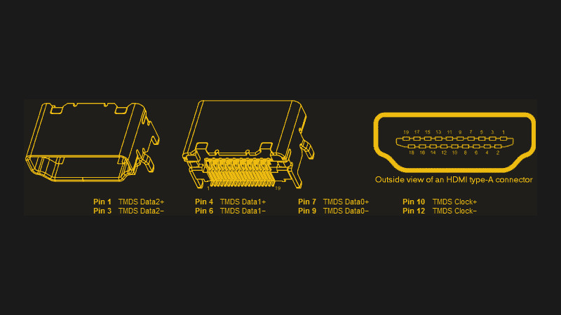
TMDS, or Transition-Minimized Differential Signaling, is the core method used by DVI and classic HDMI video transport. The encoder takes 8-bit color channel data and turns it into 10-bit symbols designed to reduce transitions and help maintain DC balance. In plain English, TMDS tries to send high-speed data without making the signal lines behave like caffeinated spaghetti.
An FPGA HDMI transmitter usually has three data channels for red, green, and blue, plus a clock channel. During active video, those three channels carry pixel color. During blanking intervals, they carry control symbols or, in fuller HDMI designs, audio and auxiliary data. This separation is important because a monitor expects not only the right pixels, but also the right silence between pixels. Monitors are strict like that. They may forgive your cable management, but not your timing.
Serialization: Where Things Get Fast
After TMDS encoding, each 10-bit symbol must be serialized. For a 25.175 MHz VGA-style 640×480 signal, the serialized bit rate is manageable on many FPGA boards. For 720p and 1080p, the bit rate becomes much more demanding. FPGA families handle this differently. Some use dedicated serializer blocks, DDR output registers, PLLs, or SERDES resources. Others rely on clever logic and board-specific constraints. This is where open source code is especially helpful: you can see exactly how a design maps abstract video concepts into real I/O primitives.
Vendor IP often hides these details behind a polished interface. That can be useful in production, but it is not always educational. An open implementation lets you follow the signal path from “draw a white pixel here” to “ship a 10-bit TMDS word out of this physical pin at terrifying speed.” For learners, that visibility is gold.
Open Source Projects Worth Knowing
The open source FPGA video ecosystem is broad, and each project tends to emphasize a different philosophy. Some are compact teaching examples. Some are reusable IP blocks. Some are parts of larger system-on-chip frameworks. Together, they show how flexible FPGA video design can be.
hdl-util HDMI
The hdl-util HDMI project is notable because it aims to send both video and audio over HDMI from an FPGA. It is often discussed as a more complete open source HDMI implementation rather than merely a DVI-compatible video output. For developers who want to understand HDMI 1.4-style packet handling, audio transport, and real-world FPGA output, this kind of project is extremely valuable.
The practical appeal is simple: instead of buying a closed HDMI IP block, you can inspect the HDL, run simulations, adapt the code to your board, and learn the structure of the interface. That does not magically remove every legal or compliance concern for commercial products, but it does remove the fog around how the hardware works.
Project F Display Work
Project F has become a favorite learning resource for FPGA graphics because it explains video timings, drawing methods, framebuffers, and display output in a clear engineering style. It is especially useful for developers who want to build up from simple test patterns to sprites, framebuffers, and practical display controllers. The Project F approach reminds us that HDMI output is not just about the connector. You also need something meaningful to display, preferably more impressive than a rectangle that took three hours to center.
LiteX and LiteVideo
LiteX is an open source SoC builder used to assemble FPGA systems with CPUs, buses, memory controllers, and peripherals. In video-oriented designs, LiteX and related LiteVideo components can help integrate display pipelines into larger FPGA systems. This is useful when HDMI is part of a broader embedded platform rather than a stand-alone demo. For example, a soft CPU might configure registers, memory might hold a framebuffer, and FPGA logic might stream pixels to an HDMI output.
Minimal DVI/HDMI Framebuffer Cores
Minimal framebuffer cores focus on a practical goal: fetch pixel data from memory and convert it into a TMDS-friendly stream. These projects are excellent references because they show the engineering tradeoff between simplicity and flexibility. A framebuffer gives software or a CPU a familiar way to draw graphics, but it also consumes memory bandwidth. Direct pixel generation uses fewer memory resources, but is less flexible for complex scenes. As usual in hardware design, the answer is “it depends,” which is engineer-speak for “welcome to the spreadsheet.”
Key Building Blocks of an FPGA HDMI Transmitter
A typical open source HDMI or DVI-compatible transmitter design includes several major modules. The names vary from project to project, but the architecture usually follows the same basic flow.
1. Clock Generation
The design needs a pixel clock and a faster serialization clock. PLLs or clock managers generate these frequencies from the board oscillator. Good clocking is non-negotiable. If the pixel clock is wrong, the display may refuse to sync, show a distorted image, or stare back at you with the cold black screen of judgment.
2. Video Timing Generator
The timing generator counts horizontal and vertical positions. It produces active-video flags, sync signals, and pixel coordinates. This module decides when the current pixel is visible and when the signal is in blanking. Many FPGA graphics demos start here because once you have reliable coordinates, you can draw test patterns, bars, gradients, sprites, and text.
3. Pixel Pipeline
The pixel pipeline creates or fetches color values. In a simple demo, color may come from coordinate math. In a game console project, it might come from tile maps and sprites. In a camera project, it may come from a sensor pipeline. In a framebuffer design, pixel data comes from RAM. The HDMI output stage does not care whether the pixel is a Mandelbrot fractal or a panic-induced magenta square. It only wants red, green, and blue at the right time.
4. TMDS Encoder
The TMDS encoder converts each color channel into 10-bit symbols. During active video, it encodes pixel data. During blanking, it emits control codes. In a fuller HDMI implementation, blanking periods may also be used for data island packets carrying audio and auxiliary information.
5. Serializer and Output Buffers
The serializer sends TMDS bits out through FPGA pins using high-speed differential signaling or suitable board-level transmitter hardware. Some boards connect FPGA pins directly to HDMI connectors through resistors or level-shifting networks. Others use external transmitter chips such as DVI/HDMI bridge devices. Board design matters greatly here. HDMI may be digital, but physics still charges rent.
DVI-Compatible Output vs. True HDMI
Many FPGA boards advertise HDMI output, but the underlying design often generates DVI-compatible video. This is not a scandal. It is a practical solution. DVI video over an HDMI connector is widely accepted by displays, easy to understand, and perfect for many projects. If your goal is to show graphics, game output, instrumentation, or a user interface, DVI-compatible TMDS may be all you need.
True HDMI becomes important when you need audio, infoframes, colorimetry metadata, or compatibility behaviors beyond basic video. Open source implementations that support these features are more complex because they must handle packet scheduling, checksums, audio clock regeneration data, and other details. The reward is a richer interface that behaves more like a consumer HDMI source.
For hobby projects, education, retro computing, and many lab tools, DVI-style output is often the fastest path to success. For product development or deeper protocol research, a fuller HDMI implementation provides a better foundation. Either way, open source helps developers see what is happening instead of waving incense at a vendor core.
Hardware Choices: Which FPGA Boards Make Sense?
The best FPGA board depends on target resolution, toolchain preference, budget, and whether you want direct HDMI output or an external transmitter. Xilinx/AMD, Intel/Altera, and Lattice-based boards have all been used for HDMI-style projects. Development boards such as Digilent’s video-capable boards are popular because they include useful connectors, clocking resources, memory, and reference designs.
Lattice iCE40 boards are attractive for low-cost learning, but they are limited in logic and speed. Lattice ECP5 boards provide more resources and are popular in open source FPGA circles because of strong support from Yosys, nextpnr, and Project Trellis-style flows. Xilinx 7-series boards offer strong I/O and mature vendor tools, while Intel Cyclone boards remain common in classrooms and hobby labs. Each ecosystem has tradeoffs: open toolchains, vendor primitives, documentation quality, board availability, and how many forum posts exist from someone who already suffered on your behalf.
External Transmitter Chips
Some designs use dedicated transmitter chips such as the Texas Instruments TFP410 or Analog Devices HDMI transmitters. This can simplify the FPGA side by moving TMDS serialization and electrical compliance into a specialized device. The FPGA sends parallel pixel data, syncs, and clocks; the chip handles the high-speed output. The downside is extra hardware, board complexity, configuration, and sometimes less educational exposure to the physical signaling details.
For production hardware, transmitter chips can be attractive because signal integrity and compliance are easier to manage. For learning, direct FPGA TMDS output is more revealing. It is the difference between driving an automatic car and assembling the transmission first. Both get you moving; one involves more coffee.
Licensing and Compliance: The Part Nobody Puts on a T-Shirt
Open source HDL does not automatically mean you can sell an HDMI-branded product without thinking about licensing, trademarks, compliance testing, or adopter agreements. HDMI is a controlled specification with formal licensing structures. For private experimentation, education, and internal research, open source implementations are incredibly useful. For commercial products, legal review is wise.
This distinction is important because engineering success and market permission are not the same thing. Your FPGA may generate a valid-looking signal, your monitor may display it beautifully, and your demo may impress everyone in the lab. But if you plan to ship hardware with HDMI branding or claim formal compliance, you need to understand the official requirements. Hardware lawyers may not be as fun as oscilloscopes, but they are cheaper than avoidable trouble.
Why Open Source Matters for FPGA Video
Open source FPGA HDMI work matters for three reasons: learning, portability, and trust.
First, learning. Video interfaces are a fantastic way to understand digital design because errors are visible. If your timing is wrong, the screen complains immediately. If your colors are swapped, your test pattern turns into modern art. If your serializer misbehaves, the display vanishes into darkness. This feedback loop is frustrating but powerful.
Second, portability. Open HDL can be adapted across boards, FPGA families, and toolchains. It may still require platform-specific serializer modules or constraints, but the high-level architecture is not locked away. Developers can port timing generators, pixel pipelines, and encoders to new hardware.
Third, trust. When a system is open, engineers can inspect it. They can verify assumptions, find bugs, improve documentation, and remove mystery. Closed IP can be useful, but open IP builds community knowledge. That community knowledge is why a student today can learn in a weekend what once required a stack of confidential documents and a meeting room full of serious people.
Practical Example: A Simple HDMI Test Pattern
A first FPGA HDMI project should be boring on purpose. Start with a known resolution such as 640×480 or 720p. Generate the correct pixel clock. Build horizontal and vertical counters. Create color bars based on the current x-coordinate. Feed red, green, and blue values into the TMDS encoder. Serialize the outputs. Constrain the pins correctly. Then connect a monitor and prepare for either joy or character-building.
Color bars are useful because they reveal channel order, bit alignment, timing, and display sync. A checkerboard pattern can expose scaling or coordinate mistakes. A moving box can confirm frame timing. Text output can test pixel pipelines. Once those work, you can add a framebuffer, sprites, audio packets, or live video processing. The trick is not to build the entire moon rocket before confirming the wheels spin.
Common Problems and Debugging Tips
Black Screen
The classic. Check the pixel clock, reset polarity, pin constraints, sync timing, and whether your monitor supports the selected mode. Try a lower resolution first. Many HDMI problems are not philosophical. They are one incorrect constant wearing a trench coat.
Wrong Colors
Red and blue may be swapped, bit ordering may be reversed, or the pixel pipeline may be feeding incorrect channel data. Use simple full-screen red, green, blue, white, and black tests before attempting complex graphics.
Unstable Image
Look for clock jitter, incorrect porch values, serializer timing issues, or poor signal integrity. Short cables and conservative resolutions help during early testing. Your first HDMI bring-up is not the time to use the mystery cable from the drawer labeled “probably fine.”
Works on One Monitor, Fails on Another
Displays vary in tolerance. A TV may accept a slightly odd signal while a capture card rejects it, or vice versa. Use standard VESA/CTA timings when possible. Read EDID later if your design supports it, but begin with a fixed mode known to work broadly.
Experience Notes: What Building Open Source HDMI on an FPGA Teaches You
The first lesson is humility. HDMI looks simple from the outside because the connector is familiar. You plug in a cable, the screen lights up, and everyone acts like tiny synchronized data rockets are not flying through copper at absurd speeds. When you implement HDMI on an FPGA, that illusion disappears. Suddenly, every pixel has a deadline, every clock has an opinion, and every constraint file becomes a sacred text.
The second lesson is that simulation is your friend, but hardware is the final boss. You can simulate counters, TMDS encoders, packet scheduling, and reset behavior. You should. Simulation catches many mistakes before they escape into the lab. But a simulated monitor is more forgiving than a real display, and real boards introduce I/O standards, pin placement, clock routing, cable quality, and signal integrity. The first time a design passes simulation but fails on hardware, do not panic. This is not failure. This is tuition.
The third lesson is to build in layers. Start with one resolution. Then one test pattern. Then stable color. Then motion. Then a framebuffer. Then audio. Then fancy features. Developers often fail because they combine too many unknowns at once. If the display is black, and you changed the PLL, serializer, timing table, pin constraints, and pixel generator in the same commit, congratulations: you have created a murder mystery where every character had motive.
The fourth lesson is that open source code teaches best when you read it slowly. Do not just copy a module and hope the monitor applauds. Trace the pixel clock. Follow the active-video signal. Watch how blanking intervals map to control codes. Look at how the serializer loads each 10-bit word. Study board-specific sections carefully, because the same logical design may need different output primitives on different FPGA families.
The fifth lesson is documentation saves weekends. Write down the exact board, FPGA part, toolchain version, clock input, target resolution, cable, and monitor model. Record what worked and what failed. HDMI bring-up can involve tiny details, and future-you will not remember whether the working build used 74.25 MHz, 75 MHz, or “that one PLL setting I clicked while tired.” Future-you deserves kindness.
The sixth lesson is that the open source FPGA community is part of the toolchain. Blog posts, GitHub issues, forum discussions, reference manuals, and example projects are often the difference between progress and staring into the void. Someone else has probably fought the same sync polarity dragon. Read generously, test carefully, and when you solve a weird problem, document it for the next person.
Most of all, implementing HDMI on an FPGA teaches the joy of visible hardware. A blinking LED is nice. A UART log is useful. But a monitor showing pixels generated by your own logic feels different. It is immediate, colorful proof that your counters, clocks, encoders, serializers, and constraints are all dancing in step. And yes, the first successful image may just be color bars. That is fine. In FPGA land, color bars are basically fireworks with better timing discipline.
Conclusion
An open source HDMI implementation for FPGAs gives developers more than a way to connect a board to a display. It opens a practical path into digital video, high-speed signaling, hardware timing, reusable IP design, and real-time graphics. Whether you are building a retro console scaler, a camera interface, an embedded dashboard, a test-pattern generator, or simply trying to understand why monitors are so picky, open source HDMI cores provide a rare combination of usefulness and transparency.
The best approach is to start simple, respect the timing, choose the right board, and treat every black screen as a solvable clue rather than a personal insult from the HDMI gods. With open HDL, strong community examples, and patient debugging, FPGA-based HDMI becomes less mysterious and far more fun. It is still serious engineeringbut the kind where success ends with actual pixels on an actual screen, which is hard to beat.