
A cheap Doppler radar module is a little like a brilliant intern on the first day: full of potential, slightly mysterious, and completely useless until you give it the right supporting system. On its own, a Doppler module may transmit microwave energy, receive reflections, and produce a tiny signal that technically contains motion information. But “technically” is doing a lot of work here. Without the right circuit, that signal often looks like nervous static wearing a fake mustache.
The real magic happens in the analog front end. A well-designed amplifier, filter, comparator, and power layout can turn a bare Doppler radar module into a useful motion sensor, speed detector, occupancy trigger, or experimental maker project. The module supplies the physics. The circuit supplies the manners.
This is why the title matters: the right circuit turns Doppler module into a sensor. Not the flashiest circuit. Not the circuit copied blindly from a questionable datasheet. The right one. In practical electronics, that difference can separate a clean detection pulse from a weekend of yelling at an oscilloscope while your coffee gets cold.
What a Doppler Module Actually Does
A Doppler radar module works by transmitting a radio-frequency signal and listening for reflections from nearby objects. When an object moves toward or away from the module, the reflected signal shifts in frequency. That frequency shift is the Doppler effect, the same basic phenomenon behind the changing pitch of a passing siren, except here we are dealing with electromagnetic waves instead of sound.
Low-cost modules such as the HB100 or CDM324 are popular because they put the microwave front end on a tiny board. The HB100 is commonly associated with X-band operation around 10.525 GHz, while compact K-band modules such as the CDM324 operate around 24 GHz. These boards usually include the oscillator, antenna structures, and mixer needed to generate an intermediate-frequency output related to motion.
That sounds delightfully plug-and-play until you meet the output pin. The useful signal coming out of these modules can be extremely small, noisy, and sensitive to power supply quality. It is not usually the kind of signal you can feed directly into a microcontroller input and expect applause. The module whispers. Your microcontroller expects someone to use their indoor voice at least. The circuit in between is the translator.
Why the Datasheet Circuit Is Not Always Enough
Many inexpensive Doppler modules arrive with a suggested application circuit. Sometimes it works well enough for simple demonstrations. Sometimes it works only in the same way a cardboard umbrella works: briefly, under ideal conditions, and with a lot of optimism.
The problem is not that datasheets are useless. Good datasheets are engineering gold. The issue is that some low-cost modules circulate with minimal, copied, outdated, or oversimplified reference circuits. A Doppler module’s IF output may require careful amplification, high-pass filtering to reject drift, low-pass filtering to remove high-frequency garbage, and stable biasing so the downstream electronics do not panic.
If a circuit amplifies too little, the signal disappears into noise. If it amplifies too much, the amplifier saturates and turns everything into a square-edged mess. If the filter bandwidth is wrong, slow body motion may be removed or fast movement may be distorted. If the power rail is noisy, the circuit may detect your voltage regulator instead of the person walking through the room. Congratulations, you have invented a power-supply mood ring.
The Core Signal Chain: From Whisper to Useful Output
The most practical Doppler module sensor circuit usually has four important stages: signal coupling, amplification, filtering, and decision-making. Each stage has a job, and skipping one is how a fun project becomes an archaeological dig through forum posts from 2013.
1. Signal Coupling
The raw IF output from a Doppler module often includes a DC component and a small AC signal. A coupling capacitor can remove the DC offset and pass the changing portion of the signal into the amplifier. This helps the circuit focus on motion rather than static bias voltage.
2. Low-Noise Amplification
The signal may need significant gain before it becomes useful. A two-stage op-amp circuit is often better than trying to get all the gain from one heroic amplifier stage. Splitting the gain can improve stability, reduce distortion, and make filtering easier. Rail-to-rail op-amps are useful in low-voltage systems, especially when the final circuit runs from 3.3 V or 5 V supplies.
3. Filtering
A high-pass filter can remove slow drift and DC wander. A low-pass filter can reject high-frequency noise outside the expected Doppler range. Together, these form a band-pass response that says, “I only care about motion signals in this useful neighborhood.” That neighborhood depends on the intended target. A person walking slowly, a bicycle wheel, and a small fan blade will not produce identical Doppler frequencies.
4. Comparator or ADC Doppler frequencies.
4. Comparator or ADC Input
Once amplified and filtered, the signal can go two ways. A comparator can convert it into a clean digital pulse for simple motion detection. An analog-to-digital converter can capture the waveform for speed estimation, FFT analysis, gesture sensing, or more advanced classification. The comparator is the doorbell. The ADC is the security camera with a spreadsheet habit.
Motion Detection Versus Speed Measurement
A Doppler module can be used in two broad ways: detecting motion or estimating speed. Motion detection only asks, “Is something moving?” Speed measurement asks, “How fast is it moving?” The second question is more demanding because it requires preserving frequency information accurately.
For simple motion detection, a filtered amplifier feeding a comparator may be enough. When motion creates a signal above a threshold, the output changes state. This can trigger a light, alarm, counter, camera, or microcontroller interrupt.
For speed measurement, the circuit should preserve the Doppler frequency without excessive clipping. The microcontroller or signal processor can then measure frequency directly or use a fast Fourier transform to identify the dominant component. That frequency can be related to velocity. In theory, this is elegant. In practice, reflections, angle, target size, and noise all join the party uninvited.
Why Frequency Range Matters
The Doppler frequency depends on target velocity, radar wavelength, and the angle between the target’s motion and the sensor. A person walking straight toward the module produces a stronger and more useful Doppler shift than someone moving sideways across the edge of the beam. This is one reason real-world testing matters.
For human motion sensing, useful Doppler frequencies may be relatively low. For faster objects, the signal frequency rises. A circuit designed only for slow motion may not work for faster targets, while a circuit designed too broadly may invite extra noise. The right bandwidth is not a decoration. It is the sensor’s attention span.
This is also why a circuit that works beautifully for detecting people in a hallway might perform poorly as a vehicle speed detector or a gesture interface. The module may be the same, but the analog front end should match the job.
Choosing the Right Op-Amp
The op-amp is the part of the circuit most likely to be unfairly blamed when everything else is wrong. Still, choosing a suitable op-amp matters. For Doppler IF amplification, designers often look for low noise, adequate gain-bandwidth product, rail-to-rail output if running from a single low-voltage supply, decent power-supply rejection, and stable behavior at the selected gain.
A slow general-purpose op-amp may work in some low-frequency motion circuits, but it can struggle when gain and bandwidth requirements increase. A very fast op-amp can work too, but speed alone does not make a design good. Layout, decoupling, input biasing, and filtering still matter. A race car with square wheels remains a poor commute.
The safest design approach is to calculate the needed gain and bandwidth, choose an op-amp with comfortable margin, and test the circuit with real targets. If the signal looks clean on a scope before it reaches the microcontroller, the firmware has a fighting chance. If the analog output already looks like haunted spaghetti, no amount of code will make it elegant.
Power Supply Noise: The Invisible Gremlin
Doppler module circuits are sensitive to power supply quality. Switching regulators, USB noise, long jumper wires, weak grounding, and poor decoupling can inject unwanted signals. Because the wanted IF signal is small, even modest supply noise can become a major problem.
Good practice includes placing decoupling capacitors close to the module and op-amp supply pins, using short ground paths, separating noisy digital switching from sensitive analog traces, and avoiding breadboard layouts for final performance evaluation. Breadboards are wonderful for blinking LEDs and proving concepts. For tiny analog signals, they can behave like an antenna farm built by raccoons.
A clean supply can make the difference between a module that detects a moving hand and one that detects the emotional state of your laptop charger. If a circuit behaves randomly, power integrity should be investigated early, not after replacing every component twice.
Layout Is Part of the Circuit
At microwave frequencies, the RF portion is already handled on the module. That is convenient. However, the low-frequency analog output still deserves careful board layout. Long high-impedance traces can collect noise. Poor grounding can create hum. Bad routing can allow digital lines to couple into the amplifier input. The schematic may look perfect while the physical board quietly ruins everything.
A practical layout keeps the sensitive input path short, places filter components close to the op-amp, uses a solid ground strategy, and keeps digital outputs away from the first gain stage. If a comparator output is switching sharply, it should not run alongside the tiny input signal like a toddler with cymbals in a library.
Comparator Thresholds and False Triggers
If the circuit is used for motion detection, the comparator threshold controls when the sensor declares motion. Set the threshold too low and the sensor may trigger from noise, vibration, fluorescent lighting interference, or general atmospheric sass. Set it too high and the module ignores real movement.
Adding hysteresis helps. Hysteresis gives the comparator separate turn-on and turn-off thresholds, reducing chatter when the signal hovers near the decision point. This is especially useful in real rooms, where signals fade, reflect, and vary with target angle.
Some applications also benefit from firmware debouncing. Instead of reacting to a single pulse, the microcontroller can require repeated activity over a short window. That tiny delay can dramatically reduce false triggers while still making the sensor feel responsive.
Doppler Modules Compared With PIR Sensors
Passive infrared sensors detect changes in infrared radiation, usually from warm bodies moving across their field of view. Doppler radar modules actively transmit and detect reflected radio waves. This gives radar modules different strengths and weaknesses.
A Doppler module can detect motion through some non-metallic materials, can work in darkness, and does not depend directly on body heat. That can make it useful in hot environments where PIR sensors may lose contrast. However, radar can also detect motion you did not intend to detect, including fans, moving curtains, vibration, pets, or activity behind thin walls.
In short, PIR is often simpler for basic room occupancy. Doppler radar is more flexible when tuned carefully. Neither is magic. Both are sensors, which means both occasionally lie with confidence.
Practical Applications for a Proper Doppler Sensor Circuit
Once the signal chain is designed correctly, a low-cost Doppler module becomes useful in many projects. It can detect human motion for lighting control, trigger a camera, monitor movement near a doorway, count passing objects, estimate speed in educational experiments, or provide motion data for interactive installations.
In maker projects, these modules are popular because they are inexpensive and surprisingly capable. A module, an amplifier board, and a microcontroller can become a compact motion sensor. With better signal processing, the same basic hardware can support speed estimation or pattern recognition.
In commercial products, radar sensing has become more sophisticated, especially with integrated mmWave chips that combine RF, analog, ADC, DSP, and microcontroller resources. But the lesson from cheap modules still applies: sensing is not just about the transducer. It is about the complete signal chain.
Common Mistakes When Building With Doppler Modules
The first common mistake is expecting a raw module to behave like a finished sensor. A bare Doppler board is not always a plug-in replacement for a PIR module. It may need amplification, filtering, shielding, and careful thresholding.
The second mistake is using a random amplifier circuit without understanding its bandwidth. A circuit copied from another project may have been designed for a different module, target speed, supply voltage, or output requirement.
The third mistake is ignoring the test environment. Radar reflections are complicated. A metal filing cabinet, ceiling fan, nearby laptop, or even the angle of a hallway can change results. Testing in one room does not guarantee identical performance everywhere.
The fourth mistake is relying entirely on digital processing to fix analog problems. Firmware is powerful, but it cannot recover information that was clipped, filtered out, or buried under preventable noise before the ADC ever saw it.
A Specific Example: Turning CDM324 Into a Useful Sensor
The CDM324 is a compact 24 GHz Doppler radar module that became popular among electronics hobbyists because it is small and affordable. The module can produce an output related to target velocity, but its raw signal needs help. Builders found that a better two-stage amplification circuit could make the output far more useful than the basic reference circuit suggested in some module documentation.
The improved approach typically focuses on clean gain, sensible filtering, and a board that physically supports the module. Once the signal is amplified properly, it can be analyzed by a microcontroller or converted to digital pulses. This makes the module suitable for projects that need motion or speed sensing within realistic limits.
The big lesson is not “buy this exact module.” The big lesson is that analog conditioning is not optional. A Doppler module may contain the microwave engineering, but it does not automatically contain a polished sensor interface.
Experience Notes: What Building With Doppler Modules Teaches You
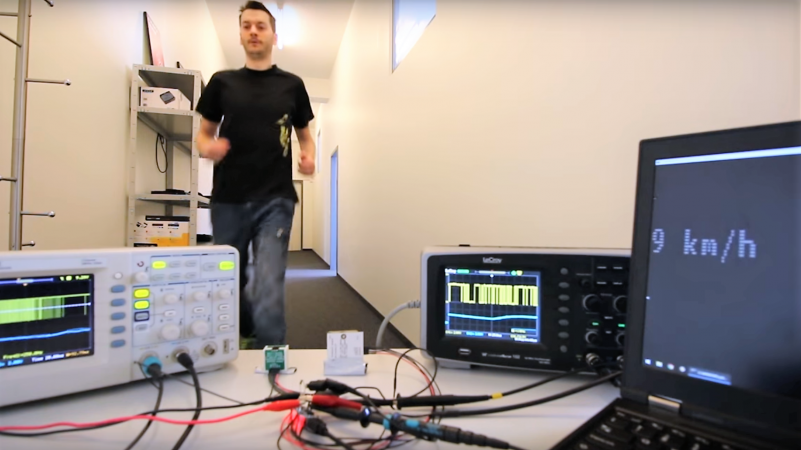
Working with Doppler modules teaches a wonderfully humbling electronics lesson: the world is noisy, and your circuit has opinions about it. The first time you connect a cheap radar module to a scope, you may expect a neat waveform that says, “A person is walking at roughly this speed.” Instead, you may see a tiny waveform riding on drift, hum, and mystery wiggles. This is normal. It is also where the real learning begins.
One useful experience is to test the module in stages. First, power the module from a clean supply and observe the raw IF output while moving a hand toward and away from it. Then add the first amplifier stage and check whether the signal grows without clipping. Next, add filtering and compare the waveform again. This step-by-step process prevents the classic beginner problem of building the whole circuit at once and then having no idea which part is misbehaving.
Another practical lesson is that physical movement matters. Walking straight toward the module gives a clearer signal than walking sideways. A hand waved close to the antenna may create a strong response, while a person at a distance may create a weaker one. Metal objects can reflect strongly. Soft objects may reflect less. The sensor is not merely detecting “presence”; it is responding to reflected energy and relative motion. That distinction explains many confusing results.
It is also worth learning to respect thresholds. A comparator circuit can make a Doppler module feel simple, but threshold selection is an art. In a quiet lab, a low threshold looks impressively sensitive. In a real room, that same threshold may trigger when a fan turns on or when someone bumps the table. Adding hysteresis and a small firmware confirmation window can make the system much more civilized.
Finally, Doppler projects teach patience with analog design. A microcontroller project can often be debugged with serial prints and stubbornness. A radar module front end asks for an oscilloscope, careful grounding, sensible layout, and a willingness to move one capacitor and test again. It can feel slow, but the reward is real: a tiny board that detects motion without light, without contact, and with just enough mystery to make the project feel like science fiction on a budget.
Conclusion: The Sensor Is the Whole System
The right circuit turns a Doppler module into a sensor because sensing is not only about detecting physics. It is about extracting a weak signal, rejecting the nonsense, and presenting useful information to the next stage. A bare module may provide a Doppler-shifted output, but a practical sensor needs amplification, filtering, stable power, thoughtful layout, and a decision method that matches the application.
For hobbyists, engineers, and curious builders, Doppler modules are excellent teachers. They demonstrate RF principles, analog signal conditioning, comparator design, microcontroller processing, and real-world testing in one compact project. They also remind us that cheap hardware can do impressive things when the surrounding circuit is designed with care.
So yes, a low-cost Doppler module can become a useful sensor. But it needs the right circuit to grow up, get organized, and stop mumbling into the noise floor.
Note: This article is written for educational electronics content and general project understanding. Builders should always follow module documentation, local RF regulations, and safe low-voltage electronics practices when testing real hardware.