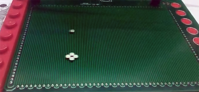

Most stepper motors are easy to picture: a round motor turns a shaft, the shaft drives a belt, screw, pulley, or gear, and the machine moves something from point A to point B. A two-dimensional stepper motor takes that familiar idea and politely removes the middlemen. Instead of spinning first and translating later, it creates direct motion across a flat plane. In other words, it can move in X and Y without the usual stack of belts, lead screws, couplings, rails, and mechanical drama.
The two-dimensional stepper motor is often described as a planar stepper motor, dual-axis linear stepper motor, or Sawyer motor. Its job is simple to explain and challenging to build: move a carriage, called a forcer, across a precision platen in controlled steps. It is a motion system that behaves like a stepper motor but thinks like an X-Y table. If a normal stepper motor is a marching band going down one street, the two-dimensional stepper motor is the same band performing a perfectly timed halftime show across the whole field.
What Is a Two-Dimensional Stepper Motor?
A two-dimensional stepper motor is an electromagnetic positioning device designed to produce controlled motion in two linear directions, usually X and Y. Rather than rotating a shaft, it moves a platform over a flat surface. The active moving part is commonly called the forcer, while the fixed base is called the platen. The forcer contains coils, magnetic materials, and often permanent magnets. The platen is typically a precision-machined steel surface with a repeating tooth pattern or grid.
The most famous version is the Sawyer motor, a type of planar motor developed for applications that need fast, repeatable positioning over a flat work area. Historically, Sawyer-style motors have been associated with equipment such as flatbed plotters, wafer probing machines, inspection systems, and precision automation stages. Modern versions are also used in pick-and-place equipment, wire bonding, fiber optic alignment, laboratory automation, electronics assembly, and other systems where compact X-Y motion matters.
The Core Idea: “Unrolling” Motion Into a Plane
A linear stepper motor is often described as a rotary stepper motor that has been “unrolled.” Instead of a circular rotor and stator, the motor uses a moving forcer and a straight platen. A two-dimensional stepper motor extends that idea across a plane. The platen is not just a toothed strip; it has a grid-like magnetic path that allows motion along two perpendicular axes.
This is why the term planar linear stepper motor fits so well. The motor does not need a separate X-axis actuator stacked under a Y-axis actuator. Both directions are built into one moving assembly and one flat working surface. The result can be a low-profile motion stage with fewer mechanical parts and less backlash than many traditional gantry systems.
How a Two-Dimensional Stepper Motor Works
The operating principle is based on electromagnetic attraction, magnetic reluctance, and controlled current sequencing. The forcer has multiple electromagnetic pole structures. When current flows through the windings, the magnetic field interacts with the toothed platen. The motor naturally seeks a stable alignment between the magnetic poles of the forcer and the teeth of the platen.
By changing the current in a carefully timed pattern, the stable point moves. The forcer follows that shifting magnetic “sweet spot,” one step or microstep at a time. This is the same basic philosophy behind stepper motors: send pulses, create discrete movement, and control position by controlling the number and timing of those pulses.
The Forcer
The forcer is the moving assembly. It typically includes the motor windings, lamination stacks, permanent magnets, electrical connections, and a mounting surface for the load. In many dual-axis planar linear stepper systems, the forcer is supported by air bearings or another low-friction bearing arrangement. The goal is to maintain a small, precise air gap between the active magnetic surface and the platen.
That tiny air gap is not a decorative detail. It directly affects force, stiffness, repeatability, and efficiency. If the gap is too large, the magnetic coupling weakens. If it is too small, the forcer may crash into the platen, and suddenly your precision motion system becomes a very expensive cheese grater.
The Platen
The platen is the stationary surface that the forcer moves across. In a two-dimensional system, it is usually machined with a square or waffle-like tooth pattern. This grid allows the magnetic field to interact with the forcer in both the X and Y directions. The platen is passive, meaning it usually does not contain powered coils. However, it is far from a simple metal plate. Its tooth geometry, flatness, pitch accuracy, surface finish, and magnetic properties strongly influence the entire system.
For high-precision applications, the platen must be manufactured carefully because any pitch error, squareness error, or surface irregularity can show up as positioning error. In other words, the forcer may be the flashy performer, but the platen is the stage manager making sure the show does not collapse.
Full Steps and Microsteps
Like rotary stepper motors, two-dimensional stepper motors can operate in full-step and microstepping modes. In full-step operation, the motor moves in larger discrete increments. With microstepping, the drive controls the current ratio between phases more smoothly, dividing each full step into smaller increments. This can reduce vibration, improve smoothness, and provide finer commanded resolution.
However, microstepping should not be confused with guaranteed absolute accuracy. It increases resolution, but real-world accuracy also depends on magnetic geometry, load, drive quality, current control, mechanical stiffness, temperature, and platen precision. A good engineer treats microstepping like a sharp pencil: it helps you draw finer lines, but it does not magically make your hand steadier.
Why Use a Two-Dimensional Stepper Motor?
The biggest attraction is direct planar motion. Traditional X-Y systems often use one linear axis mounted on another. That design works beautifully in countless machines, but it also adds mass, height, moving cables, mechanical compliance, alignment work, and wear points. A two-dimensional stepper motor can simplify the architecture by making the motor, bearing system, and positioning stage part of one compact package.
Low Mechanical Complexity
Because the motor produces direct X-Y force, it can eliminate belts, pulleys, lead screws, ball screws, gearboxes, and rotary-to-linear conversion hardware. Fewer mechanical components often mean fewer sources of backlash and less maintenance. For machines that make many short moves, this can be a major advantage.
Open-Loop Positioning
Many stepper systems are designed for open-loop operation. The controller sends step and direction commands, and the system assumes the motor follows them. For light loads and properly designed motion profiles, this can be accurate, fast, and cost-effective. It avoids the complexity and tuning effort associated with many servo systems.
That said, open-loop control has a famous weakness: if the motor is overloaded, accelerated too aggressively, or disturbed by an external force, it can lose steps. Once that happens, the controller may not know the true position unless feedback is used. For critical applications, a linear encoder or other position feedback device can turn the system into a closed-loop stage.
High Speed With Light Payloads
Two-dimensional linear stepper stages are especially useful for light payloads that need quick moves over a flat work area. Since there is no long screw to spin and no heavy gantry bridge to drag around, the moving mass can be relatively low. This helps with acceleration, settling time, and throughput.
Multiple Forcers on One Platen
One of the most interesting advantages is the ability to place multiple forcers on a single platen. Each moving head can operate independently, provided the control system and mechanical layout prevent collisions. This opens the door to parallel processing, multi-head inspection, and flexible automation layouts. Imagine several tiny robots sharing one dance floor, each knowing its own choreography and, ideally, not stepping on anyone else’s toes.
Key Applications of Two-Dimensional Stepper Motors
Semiconductor and Electronics Manufacturing
Wafer probing, die handling, wire bonding, and electronics inspection all require precise movement over a flat area. A planar stepper motor can provide the fast X-Y motion needed to position probes, cameras, bonding tools, or small parts. In semiconductor work, even tiny mechanical errors can become expensive, so the direct-drive nature of planar motion is attractive.
Flatbed Plotters and Imaging Systems
Flatbed plotters and imaging machines need controlled motion across a work surface. Historically, Sawyer motors were used in such systems because they could move a head over a plane with good repeatability and long service life. The same concept applies to scanning, marking, engraving, and optical inspection systems.
Pick-and-Place Automation
In light-duty pick-and-place machines, speed and repeatability are essential. A dual-axis linear stepper stage can move small components quickly between stations without the backlash of screw-driven stages. When paired with a Z-axis actuator or vacuum tool, it can become part of a compact assembly cell.
Fiber Optic and Laboratory Alignment
Fiber optic alignment often requires small, controlled moves with very fine resolution. Laboratory automation systems also benefit from compact X-Y motion for positioning samples, slides, sensors, or microfluidic devices. In these environments, a two-dimensional stepper motor can save space while still providing precise motion.
Advantages Compared With Traditional X-Y Stages
A traditional X-Y stage is built from two separate axes. This is common, reliable, and easy to understand. But each axis adds bearings, drive parts, structural members, and alignment requirements. A two-dimensional stepper motor integrates the motion into a single planar architecture.
- Reduced backlash: Direct electromagnetic motion avoids many mechanical transmission errors.
- Compact height: A planar motor can be lower profile than stacked stages.
- Fast short moves: Low moving mass helps with rapid positioning.
- Simplified maintenance: Fewer belts, screws, and pulleys can mean less wear.
- Scalable workspace: Travel is largely determined by platen size.
- Flexible multi-head layouts: Multiple forcers can share the same platen in some designs.
Limitations and Engineering Challenges
The two-dimensional stepper motor is clever, but it is not magic. It works best when the application matches its strengths. It is usually not the first choice for very heavy payloads, dirty environments, or applications where low cost matters more than compact precision.
Payload and Force Limits
Planar stepper motors are often optimized for light payloads. The available force depends on the forcer size, magnetic design, current, air gap, and platen geometry. If the load is too heavy or the acceleration too aggressive, the motor may lose synchronization. Good sizing requires understanding mass, friction, acceleration, move distance, duty cycle, and safety margin.
Air Supply Requirements
Many precision planar stepper systems use air bearings to maintain a consistent gap and reduce friction. Air bearings are excellent for smooth motion, but they require clean, dry, regulated compressed air. That adds plumbing, filters, maintenance, and another item for the plant technician to blame when the machine starts acting mysterious at 4:57 p.m. on a Friday.
Platen Cost and Accuracy
The platen must be flat, accurate, and carefully machined. A larger working area means a larger precision component, which can increase cost. If the platen tooth pitch is inconsistent, the motor’s positioning accuracy can suffer across the travel field.
Control Strategy
Simple open-loop control can work well for many applications, but demanding systems may require encoders, calibration maps, advanced current control, acceleration limits, and closed-loop correction. For high-accuracy path control, engineers must consider vibration, resonance, yaw, rotation, and settling time.
Open-Loop vs. Closed-Loop Operation
Open-loop operation is one of the classic advantages of stepper technology. The controller sends pulses, and each pulse corresponds to a commanded step. If the motor is properly sized and the motion profile stays within available force, the system can repeat positions without feedback.
Closed-loop operation adds position feedback, usually from an encoder. This allows the controller to verify motion, correct errors, detect stalls, and improve reliability. In a two-dimensional stepper motor, closed-loop feedback may be especially useful when loads change, accelerations are high, or the process cannot tolerate a missed step.
The choice is not about which method is “better” in every situation. It is about risk, cost, performance, and confidence. Open loop is simpler and often cheaper. Closed loop is more robust and more informative. A wise motion engineer chooses the method that lets the machine sleep peacefully at night.
Design Considerations Before Choosing One
Define the Motion Profile
Start with the basics: travel distance, move time, payload mass, acceleration, velocity, repeatability, and accuracy. A two-dimensional stepper motor may shine in short, fast, repeatable moves with light payloads. If the application involves large forces, heavy tooling, or harsh environments, another motion architecture may be more practical.
Consider the Environment
Planar motors prefer clean environments. Dust, debris, oil mist, and chips can interfere with the platen surface and air bearings. For machine tools or woodworking environments, protection becomes a major design issue. For clean labs, electronics assembly, and optical systems, the environment may be a natural fit.
Plan Cable Management
The forcer needs power and control wiring, and air-bearing systems need air supply tubing. Cable drag, stiffness, and routing can influence motion accuracy. A neat cable plan is not glamorous, but neither is debugging a beautiful motion stage that keeps tugging itself out of alignment.
Think About Calibration
For basic positioning, factory tolerances may be enough. For higher precision, calibration may be required to map platen errors, correct squareness, and compensate for repeatable geometric deviations. This is especially important in inspection or metrology systems.
Practical Example: A Compact Inspection Stage
Imagine a small electronics inspection machine. A camera must move over a flat panel to inspect solder joints, alignment marks, and component placement. A conventional design might use an X-axis rail and a Y-axis rail, with belts or screws and a moving gantry. That works, but it adds height and moving mass.
A two-dimensional stepper motor could move the camera carriage directly across a flat platen. The system could perform fast point-to-point moves, pause for image capture, then move to the next location. With microstepping, careful acceleration settings, and good vibration control, it could provide smooth motion and fast settling. If the inspection results depend on absolute position, an encoder or calibration routine could be added.
This kind of application captures the appeal of the technology: compact motion, fewer mechanical links, and efficient X-Y positioning. It is not always the cheapest path, but it can be an elegant one.
Experiences and Practical Lessons From Working With Two-Dimensional Stepper Motors
Anyone who has worked around precision motion systems learns one lesson quickly: the motor is only one member of the orchestra. The controller, drive, platen, bearings, cables, air supply, mounting surface, payload, software, and even the room temperature all get a vote. The two-dimensional stepper motor makes this lesson especially clear because it combines electromagnetic motion and mechanical precision in a very direct way.
One useful experience is to treat the platen like an optical component, not like a random steel plate. It should be handled carefully, kept clean, and protected from scratches or debris. Even a small particle on the platen can affect the air gap or motion smoothness. In a lab setting, this means clean hands, clean air, and clean habits. In a production setting, it means covers, filters, preventive maintenance, and operators who understand that the shiny flat surface is not a convenient shelf for coffee, screws, or heroic lunch decisions.
Another practical lesson is that acceleration matters as much as speed. Many teams get excited about top speed, but missed steps often happen during aggressive starts, stops, or direction changes. A stage may move beautifully at high velocity once it is already cruising, then lose position during a sharp corner or sudden deceleration. The cure is usually not mysterious: reduce acceleration, tune the motion profile, lighten the payload, increase force margin, or move to closed-loop feedback. Smooth S-curve profiles can also help because they reduce jerk and mechanical excitation.
Cable and hose routing deserves more attention than beginners expect. A forcer may be floating on air bearings with very low friction, but a stiff cable carrier can behave like an invisible spring. As the forcer moves, the cable force changes direction and magnitude, creating small errors or oscillations. In precision work, cable management is not an afterthought; it is part of the motion design. Flexible cables, balanced routing, and strain relief can make the difference between a stage that looks good on paper and one that behaves well in real life.
It is also wise to test the system with the real payload as early as possible. A bare forcer may glide beautifully, but the production tool, camera, dispenser, sensor, or vacuum head changes the mass and center of gravity. That can affect acceleration, yaw behavior, settling time, and vibration. A common mistake is validating the motion stage empty, then discovering that the final mounted tool turns the elegant planar motor into a nervous shopping cart.
Finally, two-dimensional stepper motors reward careful communication between mechanical, electrical, and software teams. Mechanical engineers care about flatness, mounting, air gaps, and mass. Electrical engineers care about current, drive settings, grounding, and noise. Software engineers care about trajectories, homing, limits, error handling, and calibration. When these teams work separately, the motor becomes a blame magnet. When they work together, the result can be a compact, fast, precise, and surprisingly graceful motion system.
Conclusion
The two-dimensional stepper motor is a fascinating answer to a classic automation problem: how do you move accurately across a flat plane without building a bulky mechanical X-Y stack? By combining a moving electromagnetic forcer with a precision grid platen, this motor creates direct planar motion that can be fast, compact, repeatable, and mechanically simple.
It is not the perfect solution for every machine. Heavy loads, dirty environments, and ultra-low-cost projects may call for more traditional approaches. But for clean, light-duty, high-speed positioning applications, the planar stepper motor deserves serious attention. It reduces mechanical complexity, supports open-loop or closed-loop control, and can make an automation system feel less like a pile of parts and more like one integrated idea.
In the world of motion control, that is a rare pleasure. After all, any machine can move. The impressive ones move with purpose, precision, and just enough engineering elegance to make the rest of us stare at the platen and say, “Okay, that’s pretty clever.”
Note: This article is intended as an educational and technical overview for web publication. Actual motor selection should be based on vendor data, payload requirements, motion profiles, environmental conditions, and application-specific testing.